Would it help to move the PSU transformer to the rear plate, further away from the input boards?
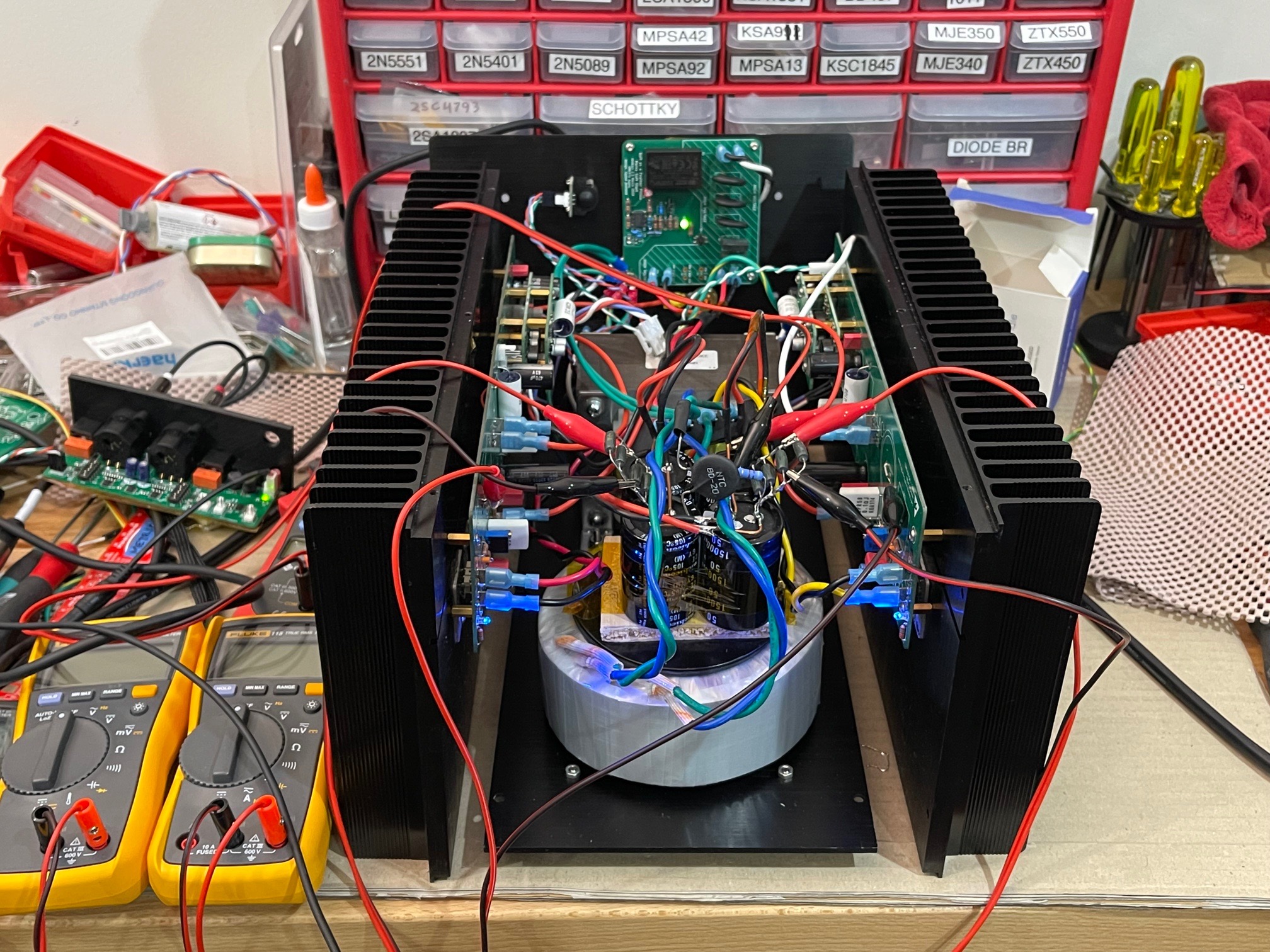
Putting the two SLBs back to back and sideways allows it to fit in this tight chassis. A dry fit without all panels bolted together is yielding higher noise already than when laid flat. Fluke 101 now reads 0.4mV rms. I can hear a little buzz - much less than before. So now the ground loop is solved but there is some spatial EMI effects of the amp going from flat to compact box. More debugging ahead.
We could try flipping the floor panel orientation 180deg. As I recall, that dropped the noise about 0.4mV or so last time. It moves the linear toroidal to the front away from the front end boards.
Having all boards with connectors (Fastons, Molex MiniFit, and Molex KK) make all of this moving around much easier than soldered flying leads during amp prototype development.
If you stick with the Antek, one of these might help. Link is here. Unfortunately, the 400 VA size seems to be out of stock at the moment.
Attachments

Would it help to move the PSU transformer to the rear plate, further away from the input boards?
That's what I suggested...
SuSyLu is a current amplifier; it needs the full voltage swing at it's input.
The design has very good PSRR.
All good things to build a quiet amp.
When it hums or buzzes, there are layout errors.
The noise as measured with Fluke 101 measures 0.1mV rms and speaker is quiet with ear pressed to cone. This is looking really promising but pushing everything back together as a small “box” may prove to reintroduce EMI induced buzz/hum. We are making progress though.
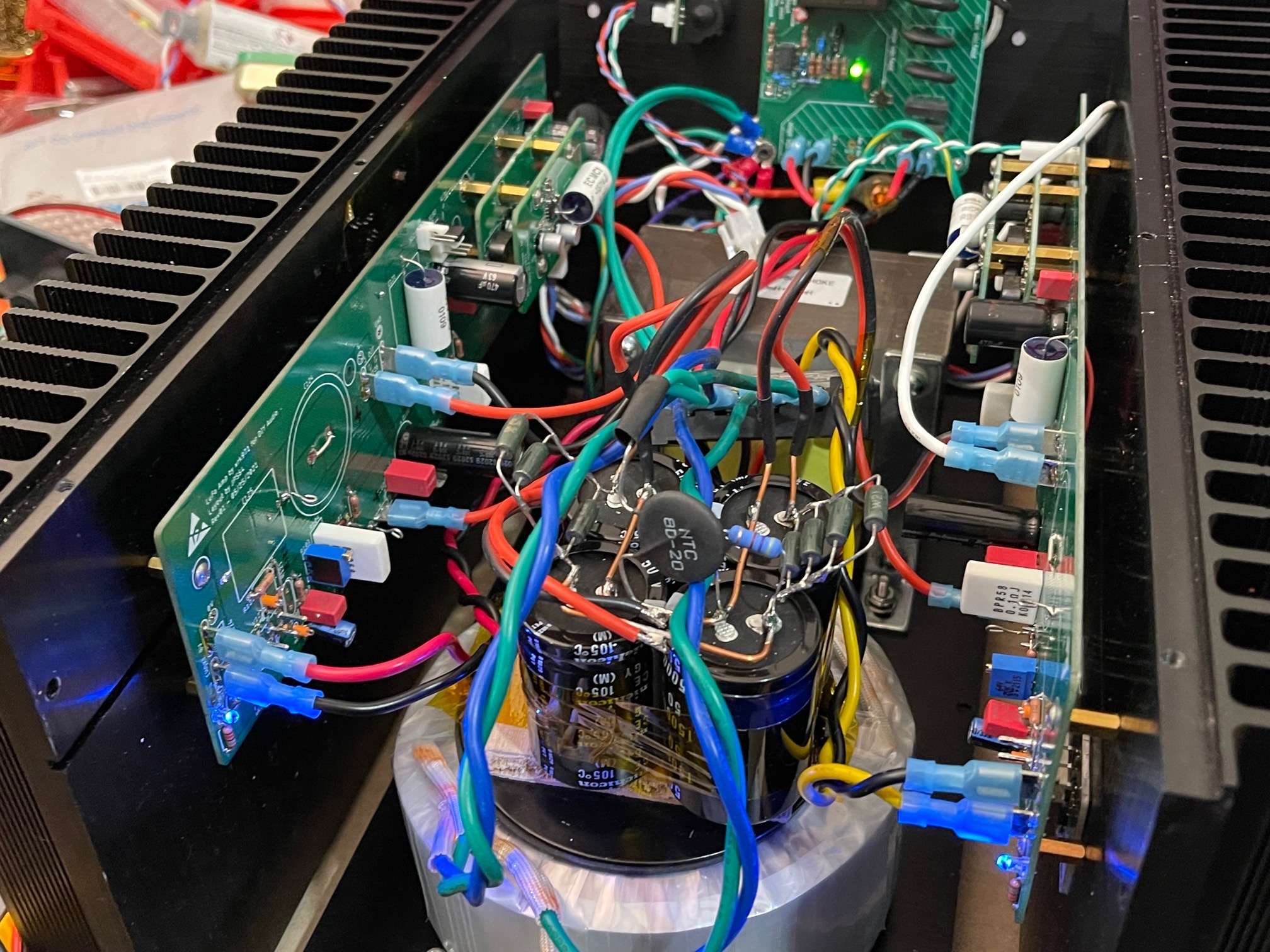
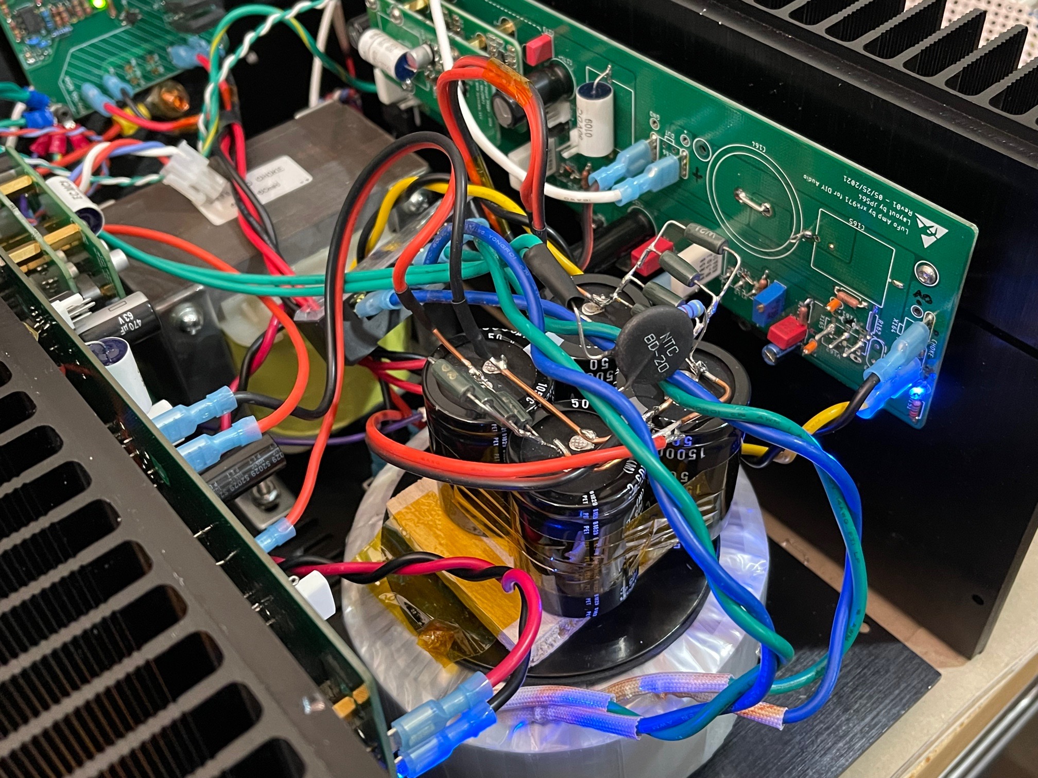
Photos show noise as measured on Fluke 101 in mV AC mode (closely matches audible buzz/hum and 0.1mV is acceptable close to silence). Photo also shows where ground pin was moved from and to.
How to interpret this in dB signal/noise ratio?
For example 28.28 VRMS@8 ohm (100 watts) related to 0.1 mVRMS giving 109 dB signal/noise ratio?
I have a custom 600VA toroidal trafo on the way. It’s much smaller than the 400VA Antek (better core material). The back panel is fully populated with jacks. Moving to the front is better as input boards are towards the rear. Standing the Antek on its side would only fit sideways (axis left to right) as space is tight with amps on the walls. I also have a SMPS coming soon. Will try all of them. The design should have inherently good PSRR, maybe a basic CRC of sufficient size is all that’s needed. I am surprised that the ground loop hum was worse with one PSU vs two PSUs.
The grounding is all controlled to star hub on back panel as can be seen in the photo. The only thing different with amp in box shape is vertical heatsinks place amp PCB closer to trafo. The longish amp board may have a larger than optimal loop area and it’s perhaps picking up EMI. The long PCB was to spread out the MOSFETs. All design space considerations. And we don’t know the problems until we assemble the amp and go through what I am doing now.
The grounding is all controlled to star hub on back panel as can be seen in the photo. The only thing different with amp in box shape is vertical heatsinks place amp PCB closer to trafo. The longish amp board may have a larger than optimal loop area and it’s perhaps picking up EMI. The long PCB was to spread out the MOSFETs. All design space considerations. And we don’t know the problems until we assemble the amp and go through what I am doing now.
That's good progress. I see that Antek does have steel cups that fit their 300VA units in stock - maybe your new (smaller) custom toroid could fit in one of those. Worth checking dimensions, perhaps.
Hi Wtnh,
Thanks for the info on the steel cover. That might be very useful. I think the 300VA one might actually fit the new custom toroidal that is on its way. I’ll have to check the final dimensions once it arrives. I just got a tracking number saying it has been shipped. That cover looks substantially thick and may block a significant amount of magnetic interference.
The 300VA one is 5.3in dia x 3.75in high.
Yes - and it weighs 5 lbs! That is a pretty substantial chunk of steel for a cover. A while ago I got a cheap off-shore cover from eBay that was super thin steel (about like a tin can), so I never bothered using it.
It looks more like a heavy duty car / truck suspension component. Like one of those cups on a rubber air suspension spring for an 18wheeler. 🙂
Thick steel is good though.
Thick steel is good though.
I have a custom 600VA toroidal trafo on the way.
Why not have a custom balanced toroidal choke wound? Put your money where it makes sense; should not be more expensive than a power supply transformer (or is your custom 600VA toroidal already for balanced choke??).
Care to respond to my former questions??
Is the residual EMI noise from the transformer itself, or is it due to the switching of the rectifiers?
The rectifiers are active MOSFETs. They are programmed to switch only at zero crossing so no switch noise. One of the biggest advantages of active bridges besides leas heat and low voltage dropout. We don’t have to deal with snubbers or “fast” diodes etc.
So I think the noise is simply radiated magnetic fields picked up by the amp board layout or wiring.
So I think the noise is simply radiated magnetic fields picked up by the amp board layout or wiring.
Checking out amp with basic CRC (15,000uF // 2x 0.33R parallel // 15,000uF) per leg. Amp is quiet without audio input from TRS balanced input. But ground loop appears when connected. Photo shows 4 resistors but I eventually removed 2.
LuFo PCB was designed for single ended non balanced operation and is perfectly quiet in that application. But using it in SuSyLu is proving to be challenging. JPS64 is looking over the layout again and perhaps a new custom PCB for balanced operation might be needed.
With CRC and no audio input connected I was getting 0.2mV rms noise with Fluke 101. Hum was not audible from speaker with ear 2in away from cone.
Last edited:
Amp is quiet without audio input from TRS balanced input. But ground loop appears when connected.
Did you use a ground loop breaker to isolate the audio GND of the amp from the chassis/safety ground of the mains power?
Did you use a "hum breaker resistor" at the input?
(See resistor R4 here as an example for what I mean by this.)
How did you connect the balanced audio source to the amp? Does pin-1 connect to the chassis or to audio GND?
Yes, chassis/mains earth (dirty) ground is isolated from 0v PSU (clean) ground via 8D-20 (8ohm) NTC. Standard practice in all my amps.
I don’t have a hum breaker resistor in the input. It’s a daughter board on the main board but the ground is tied to main PCB ground plane. This ground is connected to the PSU clean ground at the clean ground star hub on the CRC. We are looking carefully at the grounding of the input amp board and suspect the issue is somewhere here. I think the issue may be the fact that the input stage boards need to be on a separate common board so that they have low impedance ground in between them. Their low impedance outputs are then sent or the output stage PCBs. This can be tested by removing the on board HV amp daughterboards and placing them on a separate single board with common ground. Then connecting the output of that to the modules mounted on the heatsinks.
The balanced input has +ve and -ve and common shield. The common shield is shared to the two grounds of the input boards. Connecting the common grounds did no cause hum. When more than 1 signal +ve or -ve is connected, there is hum.
I also tried connecting the balanced input ground from the TRS jack to the CRC clean ground star hub and that made things worse.
So debugging continues.
Yeah, work to do (Zeus amp has -150 dB S/N ratio with a single 10 mF capacitor.....)....
You seem to like saying the Zeus does it all so well. It’s a fine and unique amp, but IMO, not the same as this one. It’s a transformer coupled input (with gain from transformer) and transformer coupled output amp - not direct balanced drive follower from a SIT with a cascode. It’s galvanically isolated inputs due to transformer coupling. This amp is DC coupled on the output. The input stage is a separate SS gain stage that is not galvanically isolated via a signal transformer.
Susan Parker’s website states 130dB SNR, btw. not 150.
It would be interesting to see the FFT on the left of 1kHz and how much 50Hz mains peak manages to get in given only 10,000uF cap for the PSU bulk capacitance.
Zeus Amp - FFT tests with 2SK1529 lateral fets
When only one leg of the SuSyLu is used (LuFo amp) with an active bridge, CRC, and capacitance multiplier PSU - this is what the FFT looks like on the left of 1kHz. The SNR is of order 115dB. I have yet to see a published FFT of a linear PSU class A amp with simple CRC achieve anything like this.
The 60Hz peak here is equivalent to about 14uV rms mains noise.
Last edited:
Getting rid of hum can be one of the most frustrating aspects of DIY audio, and building everything in a compact enclosure only complicates things. I can’t imagine working with that large inductor helps. It is kind of cheating but I think building my power supplies in separate enclosure makes life a little easier. I will send picture of dual mono supply I am building with a pair of 500 watt SMPS I purchased from Sammy.
Bill
Bill
I don’t have a hum breaker resistor in the input. It’s a daughter board on the main board but the ground is tied to main PCB ground plane. This ground is connected to the PSU clean ground at the clean ground star hub on the CRC. We are looking carefully at the grounding of the input amp board and suspect the issue is somewhere here. I think the issue may be the fact that the input stage boards need to be on a separate common board so that they have low impedance ground in between them. Their low impedance outputs are then sent or the output stage PCBs.
...
The balanced input has +ve and -ve and common shield. The common shield is shared to the two grounds of the input boards. Connecting the common grounds did no cause hum. When more than 1 signal +ve or -ve is connected, there is hum.
I also tried connecting the balanced input ground from the TRS jack to the CRC clean ground star hub and that made things worse.
I am not quite sure I fully understand your grounding scheme, but that's okay. My gut feeling is that the hum / ground loop is formed due to combining two single ended amp boards into a balanced design. Also, the balanced input should not have a "common ground". There is no audio GND with balanced inputs! The audio signal is the difference between the "hot" and "cold" wires, which are floating. The third wire/connector of the balanced cable connection must be used to connect the chassis of the source and the amp, not the audio grounds. Could this be part of your hum problem?
You seem to like saying the Zeus does it all so well. It’s a fine and unique amp, but IMO, not the same as this one. It’s a transformer coupled input (with gain from transformer) and transformer coupled output amp - not direct balanced drive follower from a SIT with a cascode. It’s galvanically isolated inputs due to transformer coupling. This amp is DC coupled on the output. The input stage is a separate SS gain stage that is not galvanically isolated via a signal transformer.
Susan Parker’s website states 130dB SNR, btw. not 150.
It would be interesting to see the FFT on the left of 1kHz and how much 50Hz mains peak manages to get in given only 10,000uF cap for the PSU bulk capacitance.
Zeus Amp - FFT tests with 2SK1529 lateral fets
Not so relevant if I like what the Zeus seems to do well.
It is more to indicate what the topology is capable of.
I have no idea if your cascode output stage has a worse PSRR compared with the Zeus output stage; both are actually source followers which have good PSRR by definition.
Your link does not show the FFT's; here another link from her audiophonics website (which by the way mentions the 150 dB SN/R but let's agree on the fact that 130 or 150 is excellent by any means):
Zeus Amp - FFT tests with 2SK1529 lateral fets
- Home
- Amplifiers
- Pass Labs
- SuSyLu Where Are You?