All good suggestions, guys. My next step was to bring trafo outside chassis. I’m quite sure that works as that simulates the flat splayed out arrangement earlier before I buttoned things up.
If you move the trafo only, you'll have long AC wires from the trafo to the amp/SLB, which might emit some 60 Hz noise into the audio circuits, and you'd still see the 60 noise. In order to avoid the possible pickup of any 60 Hz noise I'd say it's better to move all the AC stuff away from the audio circuits for debugging.
SMPS does not have a massive winding that emits large scale magnetic flux leakage.
In addition to switching probably in 400kHz range that is inaudible...
with SMPS you put the problems in the inaudible MHz range
This is all true, but... many SMPS units have variable switching frequencies in order to optimize the efficiency depending on the load. A variation of the switching frequency may show up as a modulation in the audible range. Also, even with a constant switching frequency, modulation of the switching frequency with the audio signal may cause unwanted audible effects. I compared a 50 Hz toroidal transformer with an SMPS in my Aleph-J amp. While the SMPS worked fine, the transformer PSU was better to my ears.
I think it’s the proximity of toroidal and inductor. And I did think of mumetal but that only can do so much when the two are this close together. I actually put my very last piece of mumetal in between the trafo and the SLB (that’s all I had enough for). It dropped the noise a tiny bit. But a small piece placed between the trafo and inductor actually made things worse. Like it diverted the field and concentrated it.
I think the ideal solution would be a separate chassis for the PSU altogether. Sort of like what TA did on the VFET.
https://www.diyaudio.com/forums/pass-labs/370689-diy-sony-vfet-builders-thread-141.html#post6685621
I think the ideal solution would be a separate chassis for the PSU altogether. Sort of like what TA did on the VFET.
https://www.diyaudio.com/forums/pass-labs/370689-diy-sony-vfet-builders-thread-141.html#post6685621
Thanks for that. I’ll be using a Micro-Audio SMPS and those have a topology that doesn’t care about lots of bulk capacitance at the output. Sami actually provides a free PCB to add up to 4 snap in 22,000uF caps if one wants. Not sure it is needed, but my experience with Micro-Audio is that they are very quiet. I measured the background noise floor from one of my other amps using a Micro-Audio SMPS and there was no 60Hz bump even and the floor was at -130dB on the FFT. I think drawing 6.1A continuously will raise the noise floor. But the main thing is to reduce the 60Hz EMI given off.
With good layout and proper power supply these amps should be quiet.
The aforementioned Grandinote Shinai amplifier has two independent mono amplifiers in one chassis and it was perfectly quiet; toroidal power supply transformer almost next to toroidal output choke; working with the same 3A quiescent current.
The EI choke is more vulnerable for strayfields.
Please note that rectifying voltage with these currents is quite a task for rectifiers and capacitors; check datasheets for capacitors being able to cope with these continuous currents, not all of them can.
A choke in the power supply would do well but takes money, room and weight.
Attachments
Last edited:
Looks like a steel tray holding the trafo’s above the amp might have some shielding to it. On the SLB PSU, I am using LT4320 active bridges with low RDson MOSFETs so very little heat dissipated on rectifier. The CRC needs to be looked at as it was designed for 5A continuous and had high ripple current rated caps to withstand the punishment. I measured the temp of the first cap at 51C. Still well below rated temp but everything inside the chassis is going to be about 50C given that’s how hot the heatsinks are running.
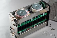
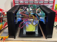
Edit, that photo shows the amp on its side. There are two banks of toroidal inductors and power trafos. Note that they are mounted with as much space in between them as possible.
Edit, that photo shows the amp on its side. There are two banks of toroidal inductors and power trafos. Note that they are mounted with as much space in between them as possible.
Last edited:
I am not sure about what technology the Micro Audio products use, but my vote for SMPS would be a design that uses quasi-resonant technology. These are much quieter and more efficient. One example is a Connex Electronic 600 Watt unit.
Last edited:
IMO the main advantage of using a SMPS is space: more distance between PS and choke.
From what I see (post #134) the power supply transformer and choke are too close; seems less than an inch; that's bad layout but difficult to correct as the depth of the chassis is the limit.
From what I see (post #134) the power supply transformer and choke are too close; seems less than an inch; that's bad layout but difficult to correct as the depth of the chassis is the limit.
To point to a classic: check how Susan Parker constructed her Zeus amplifier and see that it is important to create the necessary space between the inductive components. Her power supply is just one (high quality) single 10mF capacitor.
Zero Feedback Transformer Audio Power Amplifier - Construction
X, I'd suggest to mount the toroidal PS transformer against the back panel, and place the choke as far as possible to the front. Use the remaining space in between for a high quality 22 mF capacitor, preferably a screw type with at least 10-12A ripple current capacity.
I don't know how SLB power supply performs but 5A seems underrated, and for this type of amplifier a single capacitor should do.
Find space for the output relay board afterwards when you manage to create a quiet amp.
Last edited:
X, before resorting to all kinds of possible "solutions" to fix the 60 Hz noise: do you know where it comes from?
So far there seem to be ideas and hypotheses, but nothing really confirmed. I'd suggest to first confirm the source of the noise properly. Once you know for sure what's going on (EMI pickup in the input stage or in the choke, ground loop, whatnot), the way(s) towards a proper solution will be clear.
To repeat my earlier suggestion for debugging: start by moving all the PSU related AC far away from the audio circuits to see if the hum goes away.
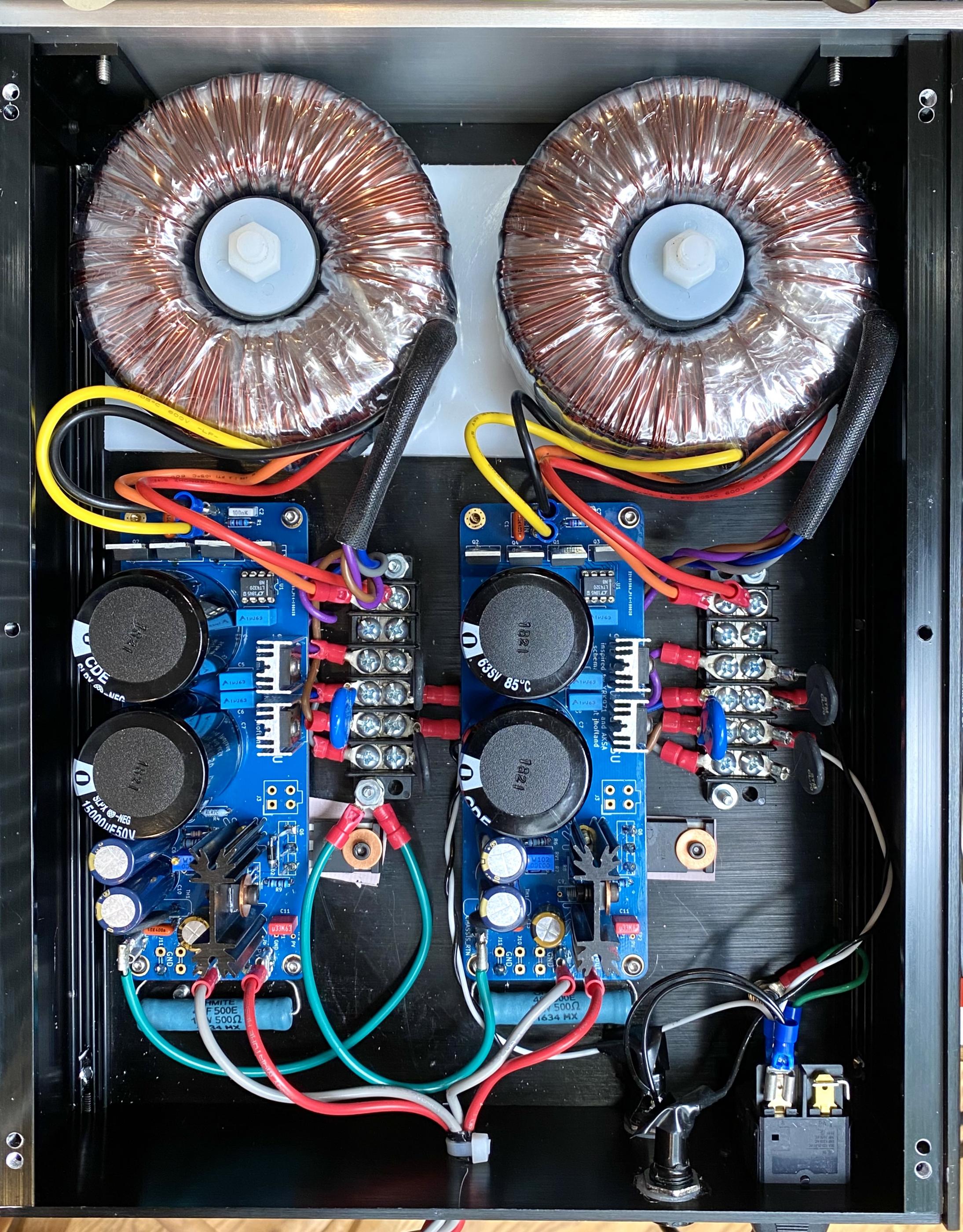
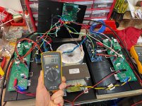
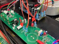
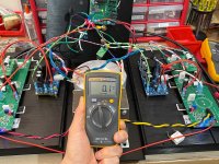
Some good progress last night. I splayed the amp open and flat. I looked at the effect of noise/buzz/hum as a function of various things. It looks like a second SLB so that each side has its own PSU seems to help a lot. Moving the toroidal trafo close to the inductor had no effect. So it looks like a ground loop due to a common PSU was one of the issues. The biggest issue, however, was a ground loop when the audio inputs from the balanced TRS connector was attached. Studying the layout of the board, JPS64 designed the layout with a star hub grounding topology at the speaker output ground for the LuFo. This ground was not used in balanced mode, and the power supply input ground was not at the star hub. We are dealing with large currents here and moving the connection for the PSU input ground to the unused star hub ground location solved the ground loop hum from the audio inputs. In flattened configuration with linear trafo next to inductor, dual SLB PSU’s, and moving ground to star hub ground location results in a quiet amp. The noise as measured with Fluke 101 measures 0.1mV rms and speaker is quiet with ear pressed to cone. This is looking really promising but pushing everything back together as a small “box” may prove to reintroduce EMI induced buzz/hum. We are making progress though.
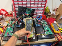
Photos show noise as measured on Fluke 101 in mV AC mode (closely matches audible buzz/hum and 0.1mV is acceptable close to silence). Photo also shows where ground pin was moved from and to.
Photos show noise as measured on Fluke 101 in mV AC mode (closely matches audible buzz/hum and 0.1mV is acceptable close to silence). Photo also shows where ground pin was moved from and to.
Attachments
-
 596AE741-2682-4385-8845-2215D466BE9C.jpg495.6 KB · Views: 234
 -
 CD9B6127-EF7C-471A-BE9D-EAA7E4B2B420.jpg481.1 KB · Views: 631
 -
 14B2D2E1-F9FF-454B-9FE8-70783D5B559A.jpg478.8 KB · Views: 610
 -
 A179ED4A-1B0C-4D1A-AE4B-7DB3E8475B10.jpeg439.3 KB · Views: 624
 -
 EE17D72A-D1BA-4D0C-9BC3-189522763FC8.jpeg864.4 KB · Views: 655
Good stuff!
Dual SLBs probably also has the benefit that you're not exceeding the output current limit of the SLB anymore, right?")
Yes, the SLB is designed to provide under 2mV rms ripple at full rated load of 5A. So 3A load should be ultra quiet (1mV or less) as far as linear PSU’s go. Also, the ripple currents in the caps will now be well under the design (optimized from simulation). The specified caps have an 8A ripple current rating, 2x higher than the predicted simulation value at 5A.
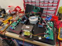
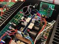
Putting the two SLBs back to back and sideways allows it to fit in this tight chassis. A dry fit without all panels bolted together is yielding higher noise already than when laid flat. Fluke 101 now reads 0.4mV rms. I can hear a little buzz - much less than before. So now the ground loop is solved but there is some spatial EMI effects of the amp going from flat to compact box. More debugging ahead.
We could try flipping the floor panel orientation 180deg. As I recall, that dropped the noise about 0.4mV or so last time. It moves the linear toroidal to the front away from the front end boards.
Having all boards with connectors (Fastons, Molex MiniFit, and Molex KK) make all of this moving around much easier than soldered flying leads during amp prototype development.
Attachments
Last edited:
- Home
- Amplifiers
- Pass Labs
- SuSyLu Where Are You?