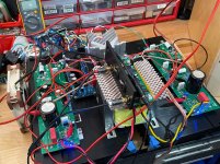
This is going going to be a tight fit to squeeze all this into this monoblock chassis.
Two LuFo boards (can skip the 10,000uF coupling cap), 400VA to 500VA toroidal trafo, a single rail SLB PSU for 6A continuous operation, the custom dual winding balanced choke, a SSR relay DC output protection board, a soft start board, and the VU meter driver board. The front end board will on mezzanine on the main LuFo boards. I hope it’s not too close to the power trafo.
Major components:
Shoehorned inside:
Each side will weigh about 45 lbs.
A link to those nice looking cabinets ?
No where close to working. Just placing components to see if everything fits.
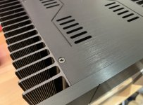
Here’s the link to the monoblock chassis. These are extremely well made. Everything fits perfectly (probably all made by a robot and CAM) and it was packed carefully and shipped via DHL express.
For example, look at the interfaces between the front panel, heatsink, top cover and screw and how tight and flush all the joints sre.
Attachments
Last edited:
Sorry about that. Try this:
2PCS MC2620 Mono Aluminium Chassis Split Amplifier Class A Amplifier Chassis|Amplifier| - AliExpress
2PCS MC2620 Mono Aluminium Chassis Split Amplifier Class A Amplifier Chassis|Amplifier| - AliExpress
Initial testing of SuSyLu using two LuFo modules connected with a common bifilar wound choke in anti phase is looking very promising. The input balanced signal is provided by the BTSB SE/Bal to SE/Bal input buffer module. I am able to achieve stable bias current settings with DC offsets under 10mV, typically closer to 2mV. Current in each leg is 3.0A and rail voltage is 27.6v from common SLB PSU (active LT4320 bridge with CRC and cap multiplier) with a solid state soft start circuit upstream. Main power is provided by an (undersized) Antek AS-4224 toroidal trafo for both legs. A larger 600VA custom toroidal trafo is on the way as well as a custom Class A SMPS to evaluate which power source is better. No turn on or off thump detected. Still running with output capacitors for now until I am certain DC offsets are stable with longer duration testing. The sound is very powerful and dynamic. Background noise is silent with music not playing. When connected to inefficient 82.4dB sensitive speakers, I can drive it very loud and no sign of inductor saturation distortion / dynamic clipping is observable. Bass is very impressive for a SE Class A amp.
Some initial videos of dynamic tracks playing pretty good volume recorded with my phone:
SuSyLu test of bass dynamics - YouTube
You can see the cone movement of the deep infrasonic bass from the London Grammar “Hey Now” track playing that would normally cause choke saturation distortion in earlier SE mode operation:
SuSyLu test of Hey Now infrasonic bass - YouTube
Attachments
Last edited:
Bass is very impressive for a SE Class A amp.
Hmm, I am wondering if this is really a single-ended amp. I see two symmetric singe-ended halves. One is pulling and the other is pushing on the dual choke and the load. I'd call this a push-pull amplifier. Nothing wrong with that, though!
No, they are a different topology with a positive rail and a negative rail and typically complementary N and P devices. That’s what traditional “push pull” is. The positive rail pushes and the negative rail pulls.
With single ended Class A, there is only one rail “pushing”, the imbalance between the two legs is then what allows the push-pull between both sides.
It is closer to bridge tied load (BTL) topology.
With single ended Class A, there is only one rail “pushing”, the imbalance between the two legs is then what allows the push-pull between both sides.
It is closer to bridge tied load (BTL) topology.
No, they are a different topology with a positive rail and a negative rail and typically complementary N and P devices. That’s what traditional “push pull” is. The positive rail pushes and the negative rail pulls.
Well... I am coming from tube amps. Push-pull seems to have a very different meaning there: both rail voltages have the same polarity, and the tubes are the same sex. If the AC signal goes positive, tube A is pushing and tube B is pulling. If the AC signal goes negative, tube A is pulling and tube B is pushing. If the output stage is biased to class-A, both tubes are operating essentially the same as the output devices in the SuSyLu, so the SuSyLu is push-pull in my mind.
Don't worry, it does not matter so much -- I was just wondering why you consider the SuSyLu as single ended, whereas my brain is wired in a different way.
Well, after a long period of searching for her, I think I have definite proof of life and have found SuSyLu...
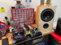
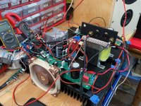
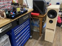
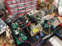
Here is a test setup to check for max output power into an air cooled 300w 10ohm EBG UXP-300 power resistor dummy load. Driven by an Akitika 2ppm 1kHz oscillator into a BTSB SE to Bal buffer, then driving the SuSyLu with OPA454 input stage.
Here is a photo of the test setup:

The red trace is the output of the BTSB buffer (balanced output) that the SuSyLu amp with front end sees. The yellow trace is the amp output after a resistive balanced divider and AC coupling caps (remember that this is a BTL output so I cannot connect the ground of my amp to any of the amp's outputs directly). According to the scope, the input signal for max output is 4.64Vpp. The output amplitude has been attenuated but the shape is correct. We will look at the Fluke 115 Vrms reading at the load resistor as 31.7Vrms, or 89.7Vpp into 10ohms. The rail voltage is 27.6Vdc (same on both legs) and bias current is 3.05A on each leg. It is pretty cool to see 90Vpp output from a 28v single rail amp. The calculated overall gain of the amp is thus 25.7dB - I think the output stage is a tad below 0dB. Note that the amp is zero global negative feedback, the feedback is only at the OAP454 front end to set the gain.
O-scope traces:
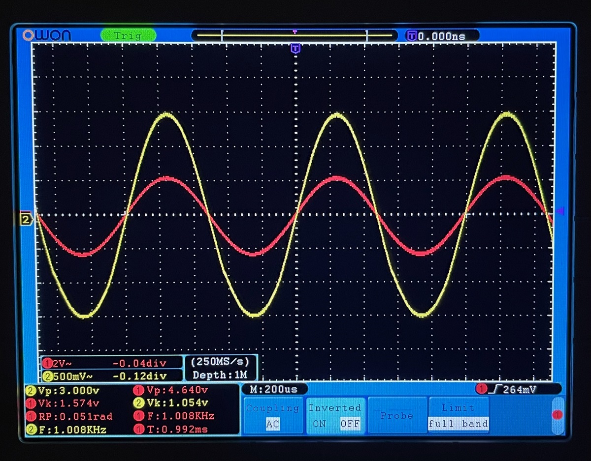
Close inspection of the output trace appears to show a slight distortion asymmetry on the falling (left side) edge of the wave about 2/3rds down - almost a slight kink in the curve. But this is asking the amp to put out max swing to demonstrate that it hits 100w.
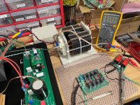
Here is a closeup of the load resistor and Fluke DMM reading. The fancy filter there is a very high order passive 100kHz low pass filter I had made for measuring class D amps - for when I take the FFT readings to come later:

The load resistor defintely needed fan cooling - it was blowing a lot of heat out. Let's look at the thermal efficiency. We have 27.6v rail x 6.1A = 168W of thermal input into the amp (not including the losses from the cap Mx in the PSU); we have 31.7Vrms into 10ohm load or 100.5Wrms. Efficiency is 100.5W/168W = 60%. That is almost approaching theoretical max of Class AB amp.
Here is a test setup to check for max output power into an air cooled 300w 10ohm EBG UXP-300 power resistor dummy load. Driven by an Akitika 2ppm 1kHz oscillator into a BTSB SE to Bal buffer, then driving the SuSyLu with OPA454 input stage.
Here is a photo of the test setup:
The red trace is the output of the BTSB buffer (balanced output) that the SuSyLu amp with front end sees. The yellow trace is the amp output after a resistive balanced divider and AC coupling caps (remember that this is a BTL output so I cannot connect the ground of my amp to any of the amp's outputs directly). According to the scope, the input signal for max output is 4.64Vpp. The output amplitude has been attenuated but the shape is correct. We will look at the Fluke 115 Vrms reading at the load resistor as 31.7Vrms, or 89.7Vpp into 10ohms. The rail voltage is 27.6Vdc (same on both legs) and bias current is 3.05A on each leg. It is pretty cool to see 90Vpp output from a 28v single rail amp. The calculated overall gain of the amp is thus 25.7dB - I think the output stage is a tad below 0dB. Note that the amp is zero global negative feedback, the feedback is only at the OAP454 front end to set the gain.
O-scope traces:
Close inspection of the output trace appears to show a slight distortion asymmetry on the falling (left side) edge of the wave about 2/3rds down - almost a slight kink in the curve. But this is asking the amp to put out max swing to demonstrate that it hits 100w.
Here is a closeup of the load resistor and Fluke DMM reading. The fancy filter there is a very high order passive 100kHz low pass filter I had made for measuring class D amps - for when I take the FFT readings to come later:
The load resistor defintely needed fan cooling - it was blowing a lot of heat out. Let's look at the thermal efficiency. We have 27.6v rail x 6.1A = 168W of thermal input into the amp (not including the losses from the cap Mx in the PSU); we have 31.7Vrms into 10ohm load or 100.5Wrms. Efficiency is 100.5W/168W = 60%. That is almost approaching theoretical max of Class AB amp.
Attachments
Last edited:
If I am reading this correctly, this is basically an H-bridge with a bifiliar transformer on the bottom legs to boost the output. Cool beans 
With this much potential energy on tap, I would expect an extra 15mF to 30mF of bulk capacitance per power rail to add some extra heft and definition to the lower octaves. It likely won't show up on a scope, but those nicer speakers should tell you something. Worth trying anyway.
With this much potential energy on tap, I would expect an extra 15mF to 30mF of bulk capacitance per power rail to add some extra heft and definition to the lower octaves. It likely won't show up on a scope, but those nicer speakers should tell you something. Worth trying anyway.
Hi TA,
Thanks for the recommendation. I’ll try more bulk caps. If anything, it will give more channel separation at the top rail.
The transformer is really a bifilar wound dual choke sharing a core. The amp is a JFET source follower with a choke load to provide reactance and increase the efficiency. It’s not really acting as a transformer other than to provide a link between the two legs (a requirement for it to be called Super Symmetric). The advantage of having a common core is for the DC magnetic flux to be cancelled with the anti phase connection. This is done all the time in push-pull tube amp output transformers, I am told.
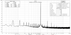
Some initial FFT measurements show that the topology works at reducing overall harmonic distortion. For 2.83vrms into 10ohms, the THD is now 0.0037% vs 0.01% for a single LuFo:
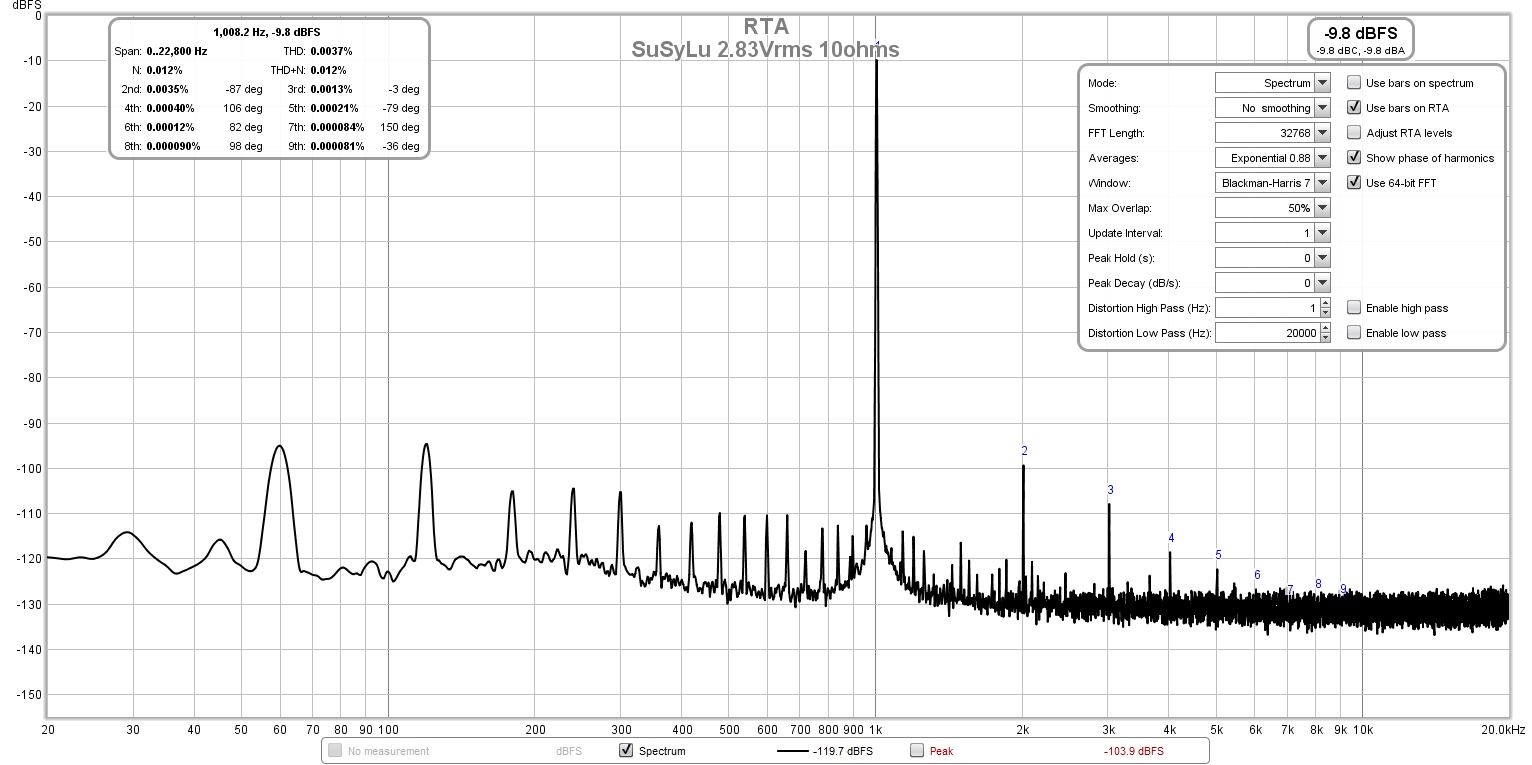
Although this is not as low as predicted in Post 1, the good news is that the harmonic profile is excellent with a dominant second harmonic and monotonically descending higher orders. I suspect that the higher second harmonic and higher overall THD is probably due to imperfect device matching. But I don't think that the increase in THD is bad given the nice profile it yielded.
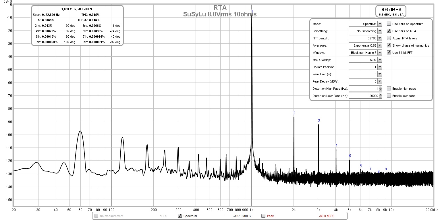
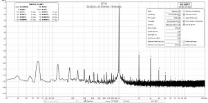
Even at a (domestically loud 8.0Vrms or 8w) the harmonic profile is still excellent and the THD is only 0.015%:
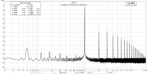
At 20.0Vrms, the harmonic profile is starting to switch over to dominant 3rd order and looking a little rough with THD at 0.23%. however, the profile is still monotonically descending higher orders:
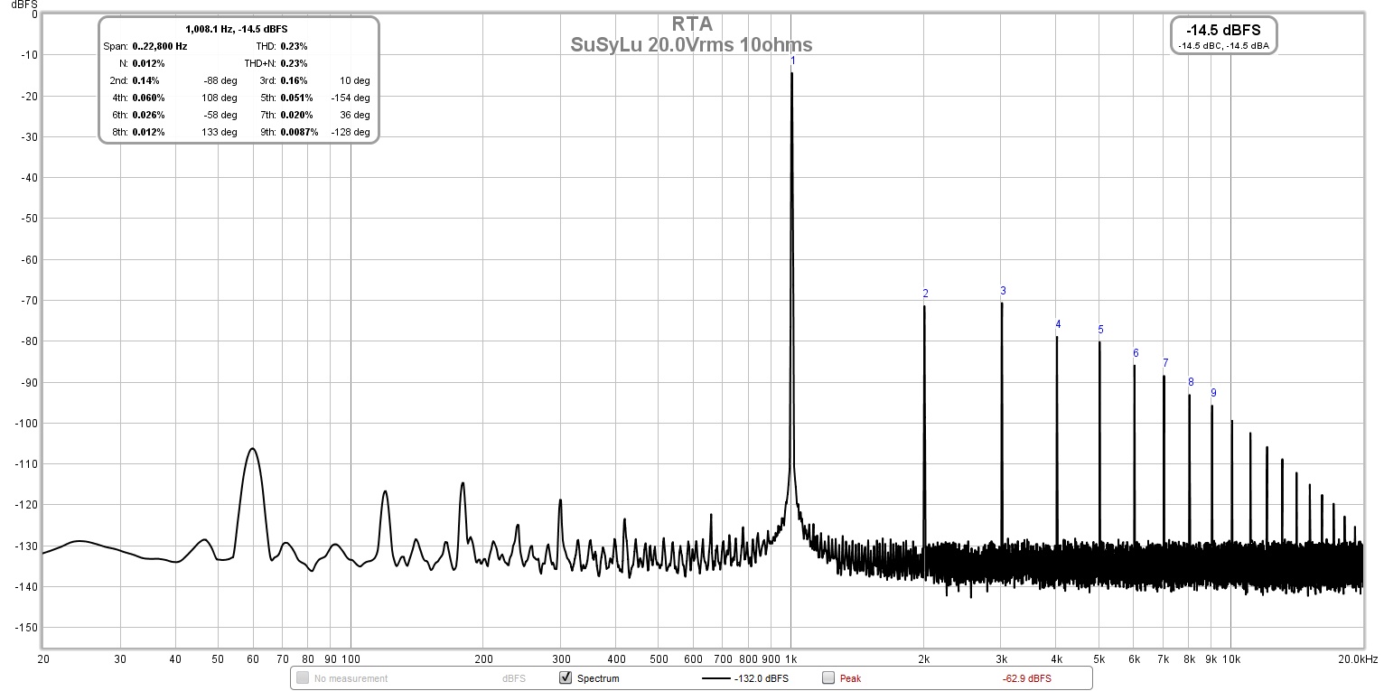
I need to work on the PSU as the 6.1A of current through the SLB does not appear to be smoothing the mains peaks at 60/120Hz, or I have a mild ground loop somewher.
Although this is not as low as predicted in Post 1, the good news is that the harmonic profile is excellent with a dominant second harmonic and monotonically descending higher orders. I suspect that the higher second harmonic and higher overall THD is probably due to imperfect device matching. But I don't think that the increase in THD is bad given the nice profile it yielded.
Even at a (domestically loud 8.0Vrms or 8w) the harmonic profile is still excellent and the THD is only 0.015%:
At 20.0Vrms, the harmonic profile is starting to switch over to dominant 3rd order and looking a little rough with THD at 0.23%. however, the profile is still monotonically descending higher orders:
I need to work on the PSU as the 6.1A of current through the SLB does not appear to be smoothing the mains peaks at 60/120Hz, or I have a mild ground loop somewher.
Attachments
Hi Wtnh,
Yes, it bothers me. The SLB was designed for 5A and at that level, the ripple is under 1mV rms. I altered the R in the CRC (nominally 0.2R but now at 0.086R) and current at 6.2A.
I soldered a jumper across the legs of the big 10,000uF output coupler caps for some DC coupled action. The bias current is amazingly stable and DC offset across the speakers was about 10mV at turn on cold. Stabilizing to about 2mV in 30min. Rock stable. I don’t think I am going to need a DC servo.
The sound quality went up several notches without the caps in place. You can hear the enhanced resolution.
amplifier’s dynamic abilities
Hi X
… After you’ve sorted the noise levels …
I came here, after seeing your very interesting post in the Nirvana thread flagging this amplifier’s dynamics.
I think it’s more appropriate to discuss that here
You’re right, while class A definitely has a few really nice attributes, it can sometimes sound too polite
What might be this amp’s unique attraction is the combination - (some degree of) the class A SE harmonic signature, details, etc * together with better dynamics.
Especially for listening to the hardest group of sounds to reproduce without losing some impact - drums. Low hz, high dB - a lot of energy. Some with very quick rise, varying decays
More so, when there’s a lot happening in the music. (Which is partly the power supply having good reserves).
Especially for enjoying harder rock, hip hop, jazz drumming …
I’m not saying anything new here, just thinking aloud of the key elements to help define how amplifier dynamics should best be assessed.
Its ability to pass a square wave, at say 60 and 150 Hz is one aspect. A tough test, but just single notes. I’m not aware of a metric which measures all of the elements of good dynamics. Certainly not in “real music”
It would be SO useful if there was an objective way to measure, ideally quantify an amplifier’s ability to render dynamics.
Even if not a “universal test” that anyone could do with standard equipment, a test that an individual DIYer, with different amplifiers - or prototypes of the one amplify - when used in combination with “their reference speaker”. which would probably make such a test more realistic and useful.
A sample of a kick drum also has harmonics, but what could we measure? The real test of course is when there is more than one high dB instrument playing at once.
A metric for this is off topic, but if anyone could comment/ point me to a thread or a link, I would really appreciate that.
I recently decided that before I take on any new projects, it would be sensible & useful to measure and compare some of my existing equipment
So, unless I’ve overlooked something …
SuSyLu - Assessing its dynamics by listening
X, you created the FAST/ WAW Monitor - with its ace of transient response
At the same 10 watts as the Pass VFET you usually use driving these speakers, how does this compare?
And with its ace of ultra low distortion, a Purifi system.
How does SuSyLu compare to say, the very low distortion RTR TPA3255?
And as you say, a good Class AB amp.
(I guess you wouldn’t have a Bryston in your collection. Almost “the reference for bass dynamics”. But not the sonic signature of a class A, in fact sometimes a little edgy)
… a Badger(??)
Do you have a particular couple of tracks you use to assess bass/ rock/ drums dynamics?
Hi X
… After you’ve sorted the noise levels …
I came here, after seeing your very interesting post in the Nirvana thread flagging this amplifier’s dynamics.
I think it’s more appropriate to discuss that here
… from what I hear, it’s very dynamic with gobs of cone slapping bass. Much like a powerful Class AB in grunt and even the way it plays rock music.
It’s unlike any SE Class A I have heard before - which I would say tends to be more “polite”
You’re right, while class A definitely has a few really nice attributes, it can sometimes sound too polite
What might be this amp’s unique attraction is the combination - (some degree of) the class A SE harmonic signature, details, etc * together with better dynamics.
Especially for listening to the hardest group of sounds to reproduce without losing some impact - drums. Low hz, high dB - a lot of energy. Some with very quick rise, varying decays
More so, when there’s a lot happening in the music. (Which is partly the power supply having good reserves).
Especially for enjoying harder rock, hip hop, jazz drumming …
I’m not saying anything new here, just thinking aloud of the key elements to help define how amplifier dynamics should best be assessed.
Its ability to pass a square wave, at say 60 and 150 Hz is one aspect. A tough test, but just single notes. I’m not aware of a metric which measures all of the elements of good dynamics. Certainly not in “real music”
It would be SO useful if there was an objective way to measure, ideally quantify an amplifier’s ability to render dynamics.
Even if not a “universal test” that anyone could do with standard equipment, a test that an individual DIYer, with different amplifiers - or prototypes of the one amplify - when used in combination with “their reference speaker”. which would probably make such a test more realistic and useful.
A sample of a kick drum also has harmonics, but what could we measure? The real test of course is when there is more than one high dB instrument playing at once.
A metric for this is off topic, but if anyone could comment/ point me to a thread or a link, I would really appreciate that.
I recently decided that before I take on any new projects, it would be sensible & useful to measure and compare some of my existing equipment
So, unless I’ve overlooked something …
SuSyLu - Assessing its dynamics by listening
X, you created the FAST/ WAW Monitor - with its ace of transient response
At the same 10 watts as the Pass VFET you usually use driving these speakers, how does this compare?
And with its ace of ultra low distortion, a Purifi system.
How does SuSyLu compare to say, the very low distortion RTR TPA3255?
And as you say, a good Class AB amp.
(I guess you wouldn’t have a Bryston in your collection. Almost “the reference for bass dynamics”. But not the sonic signature of a class A, in fact sometimes a little edgy)
… a Badger(??)
Do you have a particular couple of tracks you use to assess bass/ rock/ drums dynamics?
- Home
- Amplifiers
- Pass Labs
- SuSyLu Where Are You?