OK, I know I initially brought this up in my initial evaluations but I recently cycled my SYMEF into to listening room. Some of my initial impressions rushed back, reinforced by additional comments of my company that day. The really soft, rounded treble is what I have always wondered about. I decided to take some accurate measurements. I don't mind some subjectivism, after all that is the experience, but some objectivism is good too.
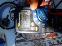
Attached is the scope shot. The amplifier was powered by +/-31V and operating into an 8 ohm resistive load. It is an image showing 10Vp-p square wave out at 100Hz where I am focussed on the leading edge. The cursors are set to 10%/90% for a voltage rise of 8V, the time cursors show a 22.4us rise time. The math says we have a 0.36V/us slew rate. An LM741C can do better!
My question is, has anyone else taken direct objective measurements of this amp? I was quite surprised by this result and am quite frankly looking to see if my build is unique (that is did I make an error killing the performance - both modules mind you) or common experience in this regard.
I can say there was some oscillation in the initial build and had to go from shunt compensation as Harrison specified to Miller compensation. There seemed to be no difference in speed, just a low oscillation riding on top of the signal prior to altering the compensation. Comments?
Maybe little too much compensated?
I haven't really experimented much since reworking the boards is a bit of a pain (I built the Type 2 boards) due to the under board mounting of the transistors.
The oscillations were in the neighbourhood of 7.2MHz and about 1.8Vp-p. I was at the beginning of my initial testing phase and had already noted significant rounding of squares, but didn't play too much knowing something was not happy. I pulled the 68pF shunt capacitors (VAS collector to ground) and installed them as traditional Miller (VAS base to collector), which cured the oscillation. Another member, Tekko IIRC, had a similar experience.
In OnAudio's defence, I did use transistors in the OPS that were handy, not the specified ones in the published BOM. I had some communication with OnAudio and he didn't seem to concerned about the substitutions. For the record, my SYMEF Type 2 boards are currently configured with the following devices:
Outputs - 2SA1265 / 2SC3182
Drivers - 2SA1306 / 2SC3298
Pre-Drivers - 2SA1507 / 2SC3902
Vbe Multiplier - BD139
I also used BC560C in place of the BC556B for the IPS. All other devices as specified.
I see a couple of possibilities, be them alone or in combination. One is the higher gain devices in the IPS can take a conditionally stable amp and make it unstable, though I'd expect the swap of B and C grades to be acceptable. Also, EF3 output stages can be unstable too, so the substitution of devices may have provoked stability issues. I may have to rework them using the specified devices and see it there's any change.
I'm still looking for actual measurement of other builds to verify if this is normal, and part of OnAudio's 'formula', or not. Also, let me reiterate that these don't sound bad, they are just different.
Correction to the above. The compensation caps are 39pF, not 68pF as stated above. I confused the value with 1DIFFQC's compensation values. Sorry for any confusion.
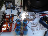
I rechecked my boards and all values seem to be good. Ran a sine wave frequency sweep to find my -3dB point is a mere 13.7kHz!
I rechecked my boards and all values seem to be good. Ran a sine wave frequency sweep to find my -3dB point is a mere 13.7kHz!
Correction to the above. The compensation caps are 39pF, not 68pF as stated above. I confused the value with 1DIFFQC's compensation values. Sorry for any confusion.
I rechecked my boards and all values seem to be good. Ran a sine wave frequency sweep to find my -3dB point is a mere 13.7kHz!
Somethings a wrong.....now lets find out what that is. Will send you a pair of type 1 to allow you flexibility
")
I may have found my issue but I won't be able to report back until a little later, this evening when I'm home from work. Rather embarrassed to say that it is possible that I may have mis-read the markings on my capacitors located at C4, the 8.2pF ones that provide some lead compensation.
I will remove them tonight and verify the values. With the way they are positioned on the board it is hard for me to read the markings, but I may have royally 'screwed-the-pooch' by possibly installing 56pF?!?. I can't seem to find my LTSpice file for SYMEF to see if simulation shows a similar result.
My sincerest apologies to OnAudio if an error on my part has skewed my findings. I will resolve the issue and re-evaluate.
I may have found my issue but I won't be able to report back until a little later, this evening when I'm home from work. Rather embarrassed to say that it is possible that I may have mis-read the markings on my capacitors located at C4, the 8.2pF ones that provide some lead compensation.
I will remove them tonight and verify the values. With the way they are positioned on the board it is hard for me to read the markings, but I may have royally 'screwed-the-pooch' by possibly installing 56pF?!?. I can't seem to find my LTSpice file for SYMEF to see if simulation shows a similar result.
My sincerest apologies to OnAudio if an error on my part has skewed my findings. I will resolve the issue and re-evaluate.
Please consider that miller cap is loading VAS driver as it works in common base mode and can not deliver more current than input stage do. Try to decrease miller cap, or take back to gnd and increase cap value to handle oscillations.
Getting it worked out.
OK, some preliminary results are in and the news is looking good.
The error was indeed the fact that the phase lead compensation capacitor, C4, value somehow ended up as a 56pF component. Sorry about that. I'm rather embarrassed that happened.
I was able to put the 39pF capacitors back into the specified shunt compensation positions. I did not have a small enough value on hand, so for the moment the C4 component location is vacant. I will get a nice mica capacitor of the correct value soon, though it seems to work fine without it.
Now for the actual measured results so far:
The HF -3dB point is now at 450kHz and the slew rate is at least 12V/µs (I need a better square wave generator) and is likely a little higher.
I need to correct the other channel and get them back into the listening room to re-evaluate. My prior comments about the unnatural soundstage and soft treble are likely to be completely invalid. I did also find my spice files and was able to confirm my prior issues in simulation and that the corrected situation aligns reasonably well between reality and the simulation.
Last edited:
Both channels corrected now. Will do some listening soon.
I had destroyed the first of the incorrect value capacitors during extraction (pliers crushed it) so I couldn't actually measure its value. The second one survived and I discovered something even worse when I measured it. They were direct marked, not EIA coded. So not only did I mistakenly install the wrong value, I found that on this particular capacitor (both were the same), marked 560K, was not a 56pF (56x10^0) +/-10% but actually 560pF +/-10%!
The moral of this tale? Unless you know the manufacturer of your capacitors, and how they mark them, it might be wise to measure them to be sure what you have. These were ones I had in my parts box and were not very well marked. I suspect I initially had mistaken the temperature coefficient code to be a 5pF capacitor, then the issue was compounded by it being direct marked. Lesson learned.
Harrison on the PCB's there is R37 from input AGND to power GND. Is this 7.5K?
It isn't on the BOM or schematic as far as I can see.
No, 7.5 ohm. It can be anything from a jumper to about 10 ohm. It is just there to lift the audio ground and prevent hum.
No, 7.5 ohm. It can be anything from a jumper to about 10 ohm. It is just there to lift the audio ground and prevent hum.
much appreciated
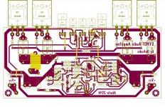
This amp was a long delayed project of mine, the reason was I have wanted a pcb design using my parts preference, notably using 2SA970 / 2SA992 at the input. This design was inspired from the early works of drowranger...  I just hope it will work fluidly when properly assembled. Schematic was drowrangers version.
I just hope it will work fluidly when properly assembled. Schematic was drowrangers version.Attachments
Happy new year. Nice work (took a quick peek)
kind regards,
Harrison.
kind regards,
Harrison.
This amp was a long delayed project of mine, the reason was I have wanted a pcb design using my parts preference, notably using 2SA970 / 2SA992 at the input. This design was inspired from the early works of drowranger...
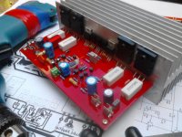
Very nice! Everything went up smoothly at power-on, excellent soundstage very similar to my Leach build but with a heavier bass punch. Pretty silent too no turn on and off thump and with all that messy wiring during test, hum problem did not occur
Thank you sir Harrison
Thank you sir Harrison
Attachments
Congratulations and very nice work.
Hope you were able to set bias. That would have been 23mV across each emitter resistor.
Keep us updated.
kind regards,
Harrison.
.Hope you were able to set bias. That would have been 23mV across each emitter resistor.
Keep us updated.
kind regards,
Harrison.
Very nice! Everything went up smoothly at power-on, excellent soundstage very similar to my Leach build but with a heavier bass punch. Pretty silent too no turn on and off thump and with all that messy wiring during test, hum problem did not occur
Thank you sir Harrison
- Home
- Amplifiers
- Solid State
- SYMEF amplifier