There seems to be enough interest in a two-way, two-part single point speaker design to warrant a post, so we'll start it with the basics and go from there. The cabinet is loaded with two B&C 10CL51 10" woofers and a Celestion CDX14-3050 three inch diaphragm 1.4" exit high frequency driver, though other similar drivers could be substituted.
Initial testing has been done using a production sample of the CDX14-3050-16, only available to OEM dealers with a minimum order of 96 units. Additional testing was done with the standard 8 ohm unit.
The B&C 10CL51 LF driver has a Fs of 60 Hz, allowing a variety of bass reflex tuning options, (or sealed), depending on what (if any) subwoofer will be used. The Neo drivers and well braced 1/2" cabinet construction result in a very light but strong enclosure, just under 35 pounds (19 kilos) for the main cabinet.
An unusual feature of the design is the second portion of the horn is separate, allowing the main cabinet to be much smaller and lighter than if it were part of the main enclosure. The secondary horn portions nest like Dixie cups, and are attached with a bridle assembly to the main enclosure. For smaller venues where cabinet size is limited and pattern flip and "waistbanding" may not be an issue, the second portion of the horn may be left off. The cabinet also incorporates an adjustable tilting stand mount.
Test results of the HF section of the cabinet are in Post #177.[/B]
Drawings of Revision 3 in Post # 98: A smaller cabinet design, with no loss in output, but some loss in horizontal pattern control, about 284 Hz compared to the previous version at 226 Hz.
The main cabinet is 26.5" x 15" deep by 11.25" tall, which results in approximately 31 liter net volume after subtracting horn, drivers, tilt stand, and port volume. The cabinet uses four bass reflex ports, each approximately 11.5" (29.2cm) long with approximately 7.5 square inch (48cm2) exit, using the 10" driver baffle board as one vertical side. The unusual port arrangement will require testing to insure the box tuning is as designed.
The preliminary drawings below have a number of errors, refer to Post # 98 and Post #177 for the design as built.
Because the initial design has evolved considerably between conception and realization, a new post with the final design has been posted:
http://www.diyaudio.com/forums/mult...ual-single-point-source-horn.html#post4114406
Art
Attachments


Last edited:
Weltersys,
I will need the volume of the cone behind the injection port in order to model this in akabak for you (use rice/beans or similar to measure volume). Also, what do you estimate the rear chamber volume to be? Will you be wiring the 3 woofers in parallel?
I will need the volume of the cone behind the injection port in order to model this in akabak for you (use rice/beans or similar to measure volume). Also, what do you estimate the rear chamber volume to be? Will you be wiring the 3 woofers in parallel?
Last edited:
This is a 2 way similar to this design
http://www.diyaudio.com/forums/subwoofers/262305-faitalpro-15hp1060-vs-3015lf-tapped-horn-39.html#post4076821
http://www.diyaudio.com/forums/subwoofers/262305-faitalpro-15hp1060-vs-3015lf-tapped-horn-39.html#post4076821
Weltersys,
I will need the volume of the cone behind the injection port in order to model this in akabak for you (use rice/beans or similar to measure volume). Also, what do you estimate the rear chamber volume to be? Will you be wiring the 3 woofers in parallel?
The easiest and cleanest method is using the cone volume calculator in Horn Response. I've found it is accurate enough that my results are well within what is predicted in my models and measurements.

Sim results v1
Using Weltersys's sketch above and making a few assumptions, I came up with the following design:
- 3.0 in dia CSA port injection holes for the qnty 3 x 10CL51's, ports located 3.0 in from throat (axial distance)
- Qnty 4 x 4.0 in dia x 8 in long bass reflex ducts ported into horn walls at 12in axial distance from throat
- Rear chamber volume is 40.4 liters based on 30in wide x 10in tall x 15in deep with pyramidal horn volume subtracted out
- Driver volume between cone and horn wall is 500 cc's (if needed make a volume filler insert - needed to extend bandwidth higher)
- Woofers connected in parallel
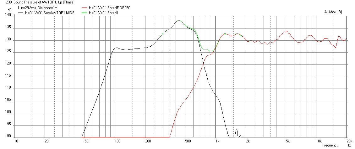
- I don't have a model of the internals of the Celestion CD, so I am using the available B&C DE250 - which will not go as low as a 3in CD diaphragm with 1.4 in throat - however, substitute later and adjust XO and EQ as needed.
The mid drivers will need to be EQ'd to level the main port injection output with the lower SPL bass reflex output. Max sustained SPL (AES rating of driver) is 127dB at 1m. 6mm xmax limited SPL (peaks) is about 132dB SPL at 1m.
Overall, I think this design is quite simple and can work well if given appropriate DSP EQ'ing and delays. I used an allpass delay of 550Hz between the HF and LF to get time alignment needed at the XO region. I am using a 500Hz 24dB/oct XO to limit the ragged peaks from the main injection port - could be made a bit higher like 700Hz and still work. A -12dB/oct HPF at 80Hz is used to limit cone excursion at low frequencies.
Max SPL at AES rating of 450 watts:
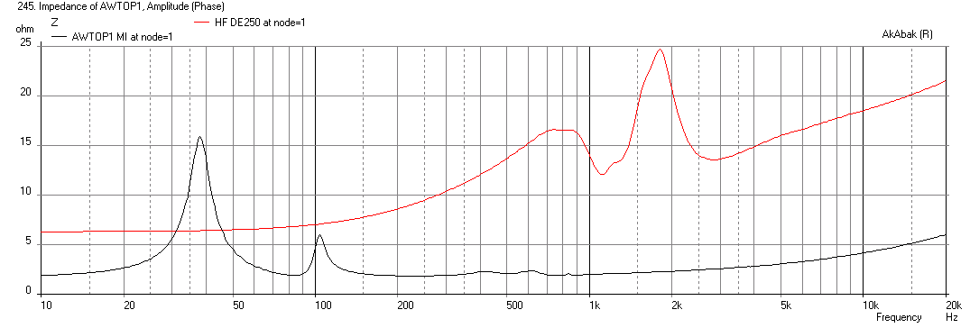
Here is Impedance:
Here is Cone Displacement at max thermal input power:

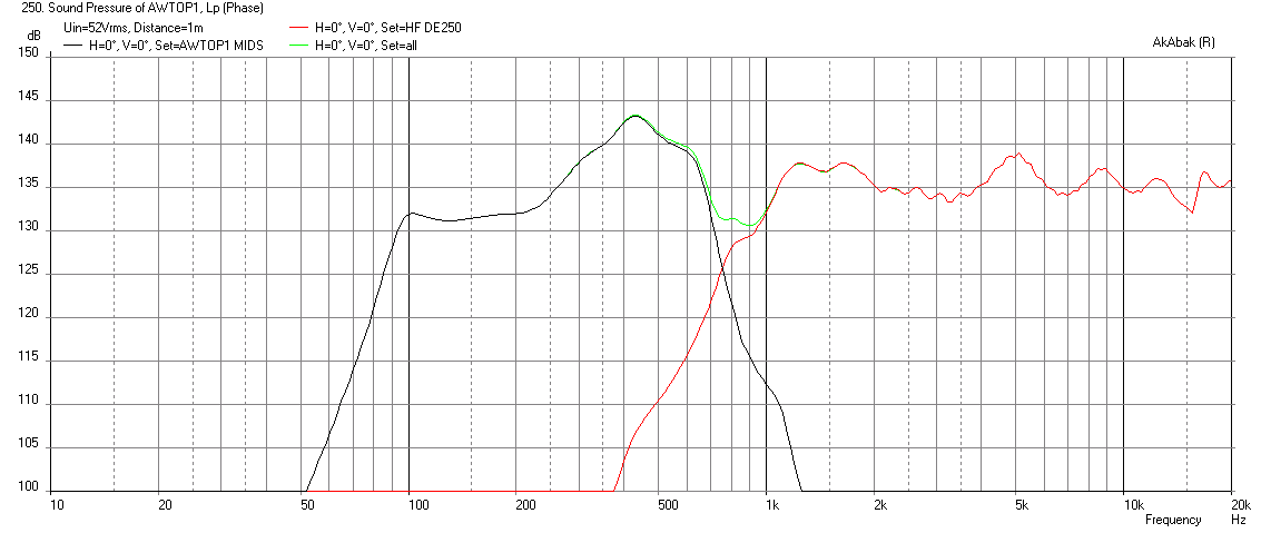
Here is corresponding peak SPL at xmax:
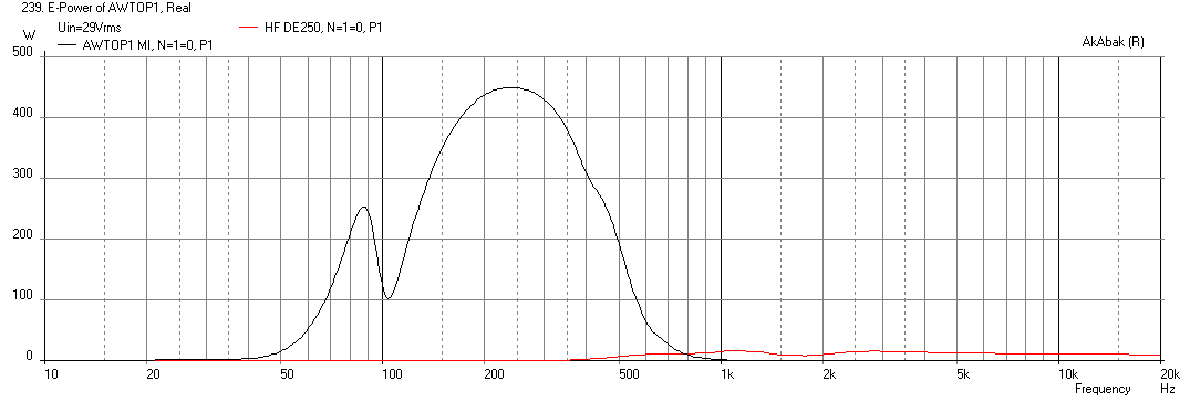
Here is Electrical Power input at max power:
Here is the response at max SPL assuming a sealed rear chamber:
Attached is the spreadsheet used to obtain the geometry for a 90deg x 35dgeg horn with a 30in wide horizontal mouth at the second expansion angle. Also attached is a scan of the geometry sketch that I am using based on the spreadsheet.
Using Weltersys's sketch above and making a few assumptions, I came up with the following design:
- 3.0 in dia CSA port injection holes for the qnty 3 x 10CL51's, ports located 3.0 in from throat (axial distance)
- Qnty 4 x 4.0 in dia x 8 in long bass reflex ducts ported into horn walls at 12in axial distance from throat
- Rear chamber volume is 40.4 liters based on 30in wide x 10in tall x 15in deep with pyramidal horn volume subtracted out
- Driver volume between cone and horn wall is 500 cc's (if needed make a volume filler insert - needed to extend bandwidth higher)
- Woofers connected in parallel
- I don't have a model of the internals of the Celestion CD, so I am using the available B&C DE250 - which will not go as low as a 3in CD diaphragm with 1.4 in throat - however, substitute later and adjust XO and EQ as needed.
The mid drivers will need to be EQ'd to level the main port injection output with the lower SPL bass reflex output. Max sustained SPL (AES rating of driver) is 127dB at 1m. 6mm xmax limited SPL (peaks) is about 132dB SPL at 1m.
Overall, I think this design is quite simple and can work well if given appropriate DSP EQ'ing and delays. I used an allpass delay of 550Hz between the HF and LF to get time alignment needed at the XO region. I am using a 500Hz 24dB/oct XO to limit the ragged peaks from the main injection port - could be made a bit higher like 700Hz and still work. A -12dB/oct HPF at 80Hz is used to limit cone excursion at low frequencies.
Max SPL at AES rating of 450 watts:
Here is Impedance:
Here is Cone Displacement at max thermal input power:
Here is corresponding peak SPL at xmax:
Here is Electrical Power input at max power:
Here is the response at max SPL assuming a sealed rear chamber:
Attached is the spreadsheet used to obtain the geometry for a 90deg x 35dgeg horn with a 30in wide horizontal mouth at the second expansion angle. Also attached is a scan of the geometry sketch that I am using based on the spreadsheet.
Attachments
-
Synergy Calc v5-AW-90-35-deg.zip499.9 KB · Views: 194
-
 AWTOP1-Freq-at-xmax-1m-sealed.png40.4 KB · Views: 3,801
 -
 AWTOP1-Electrical-Power.png27.6 KB · Views: 3,817
 -
 AWTOP1-Displacement-at-max-power.png27.7 KB · Views: 3,819
 -
 AWTOP1-Impedance.png30.3 KB · Views: 3,854
 -
 AWTOP1-Freq-max-Power-1m.png41 KB · Views: 4,065
 -
AWtop1-dims.pdf161.7 KB · Views: 301
-
 AWTOP1-Freq-at-xmax-1m.png41.7 KB · Views: 3,811
Last edited:
I guess the burning question will be what does it look like without the secondary expansion? I will run those when I get back to the AkAbak computer again.
Xrk971,Using Weltersys's sketch above and making a few assumptions, I came up with the following design:
1) 3.0 in dia CSA port injection holes for the qnty 3 x 10CL51's, ports located 3.0 in from throat (axial distance)
2)Qnty 4 x 4.0 in dia x 8 in long bass reflex ducts ported into horn walls at 12in axial distance from throat
3)Rear chamber volume is 40.4 liters based on 30in wide x 10in tall x 15in deep with pyramidal horn volume subtracted out
4)Driver volume between cone and horn wall is 500 cc's (if needed make a volume filler insert - needed to extend bandwidth higher)
5)Woofers connected in parallel
6)I don't have a model of the internals of the Celestion CD, so I am using the available B&C DE250 - which will not go as low as a 3in CD diaphragm with 1.4 in throat - however, substitute later and adjust XO and EQ as needed.
7)I am using a 500Hz 24dB/oct XO to limit the ragged peaks from the main injection port - could be made a bit higher like 700Hz and still work.
8)Attached is the spreadsheet used to obtain the geometry for a 90deg x 35dgeg horn with a 30in wide horizontal mouth at the second expansion angle. Also attached is a scan of the geometry sketch that I am using based on the spreadsheet.
Thanks for the speedy work!
1) Each of the three 10" driver would use two ports at S2, so I assume each of the six would just be the equivalent of 1/2 of a 3" diameter port hole?
2) Sounds good, that is 4" interior diameter, correct?
3) The interior main cabinet size is 29" wide x 14" tall x 18" deep, a gross volume of 4.229 cubic feet, the pyramid taken up by the first portion of the horn is 29"x14"x17", 1.331 cubic feet, 4.229-1.331=2.898 cubic feet x 28.3168=82.06 liters gross rear chamber. Subtracting three liters for the 10" drivers, and another 3.06 for ports, HF driver,bracing and stand mount leaves 76 liters net for the rear chamber. Check my math, but I think your estimate is undersized, probably because of #8 below. With the same FB, the LF response should be stronger, or a lower Fb could be chosen.
4)The spec sheet lists the driver volume as 1liter and also .03 cubic feet which would be only .85 liters, both figures smaller than listed for one of their 8" drivers, so I don't have confidence in figuring the throat chamber volume based on the spec. I think 500cc may be a bit large for the throat chamber, perhaps we can get Jennygirl to pour some rice or noodles in a BC10CL51 and get an accurate figure.
5) It would be nice to see sims of two and four 10" drivers also.
6) Perhaps you could just substitute the Sd of the CDX14-3050's 75mm diaphragm (44cm2) for the 44mm BC 250 diaphragm (15.2cm2) to get an approximation, the Xmax/Xlim of either is probably very similar.
7) It would be nice to see the raw response with a few different front chamber and port area size.
8) Your geometry sketch has a total horn length including L45 as only 45.45cm (17.89") Measured from the HF diaphragm (including the phase plug as part of the horn) from S1 to S4 would be approximately 43.18cm (17"), then the length of the separate second portion of the horn L45 (listed as 8.49) would be in addition, for a total length of 51.67 (20.34"). It appears you made the entire horn length only the depth of the cabinet, rather than the length it would be with the second portion of the horn.
It will be interesting to see what the response looks like without the second portion, and the horn length and volume adjustments.
Thanks again,
Art
Last edited:
Weltersys,
I used 4 in sch 40 PVC pipe for the ducts. The length worked out that way automatically if you spec 90x35 deg and want 30in wide at S4. I adjusted flare freq to get width. If you want to adjust to get depth that is different. I thought the 30in wide was a more dominant constraint. The extra volume should get you more deep bass. Let me check volume again.
I used 4 in sch 40 PVC pipe for the ducts. The length worked out that way automatically if you spec 90x35 deg and want 30in wide at S4. I adjusted flare freq to get width. If you want to adjust to get depth that is different. I thought the 30in wide was a more dominant constraint. The extra volume should get you more deep bass. Let me check volume again.
30"x 15" is the external width of the cabinet, the horn is actually only 29 x 14 at S4. My estimate of 35 degrees for the vertical angle may be off, just used a protracter to measure.Weltersys,
I used 4 in sch 40 PVC pipe for the ducts. The length worked out that way automatically if you spec 90x35 deg and want 30in wide at S4. I adjusted flare freq to get width. If you want to adjust to get depth that is different. I thought the 30in wide was a more dominant constraint. The extra volume should get you more deep bass. Let me check volume again.
Thanks,
Art
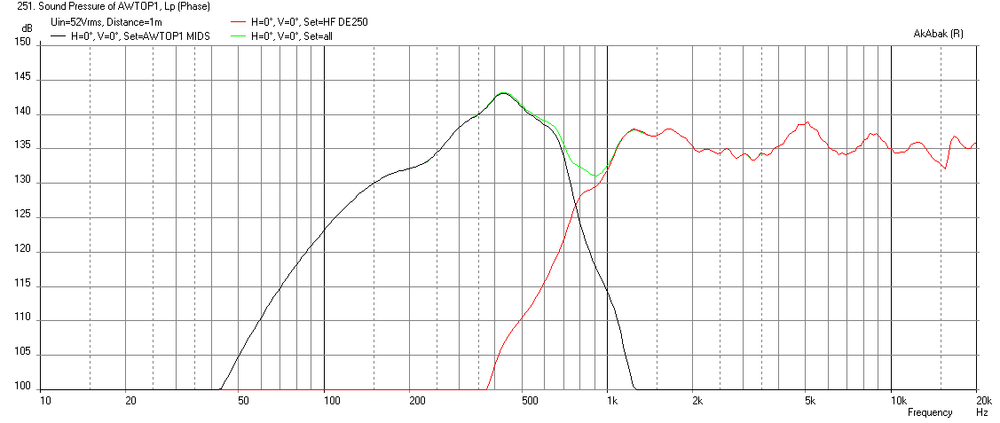
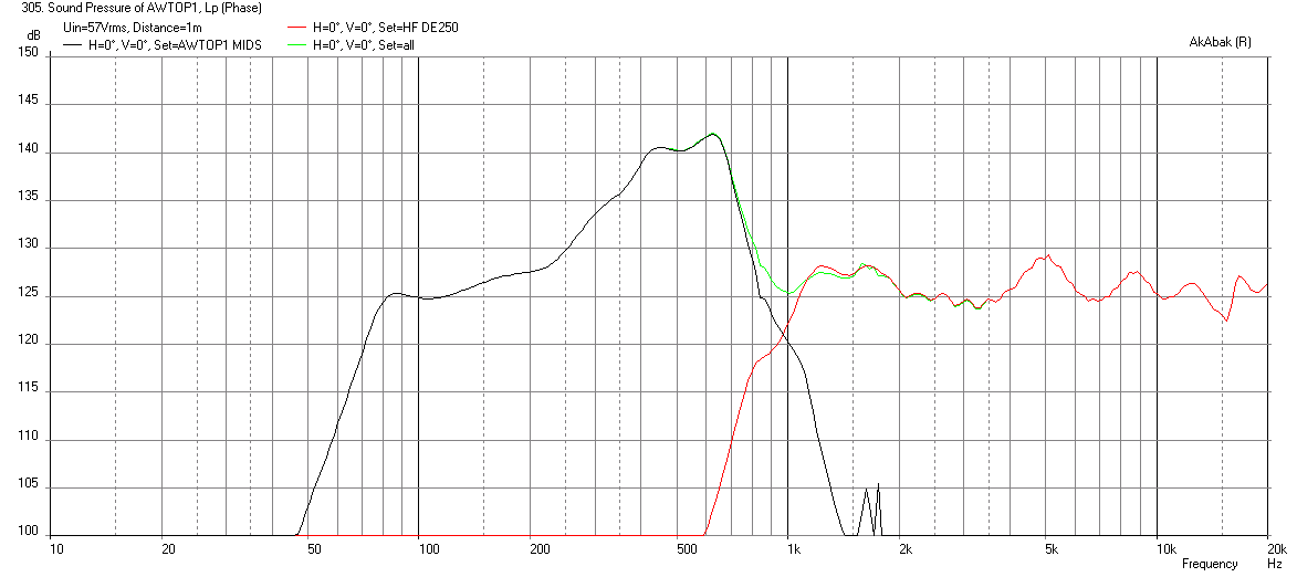
V2 with 76 liters and 4 x 10CL51's
Weltersys,
I adjusted the volume to 76 liters as you say. My volume used earlier was actually 49.4 liters based on 10in H x 15in deep x 30in W, but in any event, I used 76 liters as that probably matches the external box you were thinking of more. I added the fourth driver for series-parallel, and as expected, the sensitivity for same voltage went down but you can go to a higher voltage. The increased volume gives an 80Hz extension before it starts to fall off. Still using qnty 4 x 4.0 in x 8.0in long bass reflex vents. I also tried removing the front piece, surprisingly, you don't lose too much efficiency. The pattern control may not be as smooth, but seems like a nice compact option. XO is now at 700Hz, and -12dB/oct HPF is at 67Hz. Regarding changing the Sd on the CD - it is not as simple as changing Sd, the internal geometry of the phase plug and channels, coil diameter, Mms, etc are all involved. If you want, I can put a model of the JBL 2450 2 in CD in - I have that model somewhere. I don't think it matters as long as you know your CD can hit 700Hz for the XO. Even with the DE250, it appears that it may work at 700Hz, although not sure how accurate the model of the DE250 is.
Here is 4 drivers with 76 liter rear chamber, vol of front driver chambers are 420 cc's (adjusted to get smoothest response) at thermal AES max of 600 watts which is about 4mm stroke on the woofers:
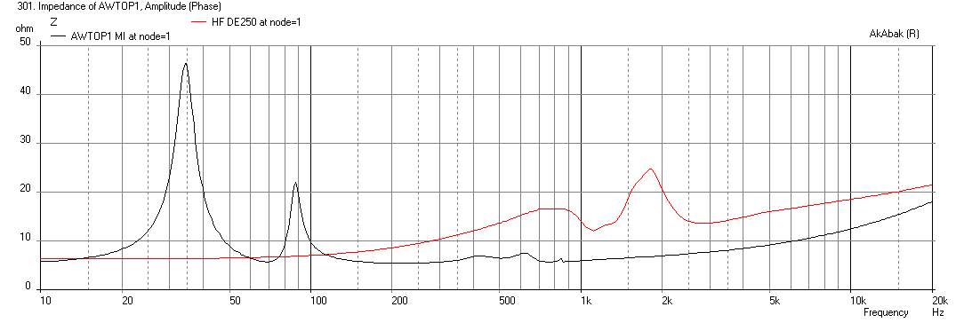
Impedance:
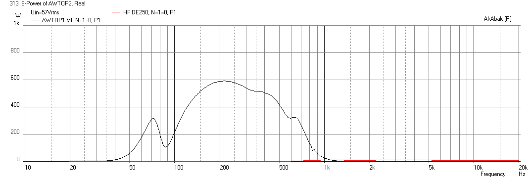
Electrical power:
Response with secondary expansion removed:

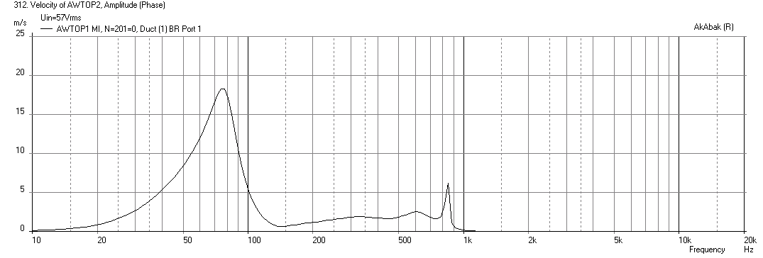
Vent velocities at max power in case you are worried about chuffing (seems ok at 17 m/s):
I hope all this helps confirm your idea for this design - I think you should go for it. Having a 2-way seems to really simplify things and keeps the costs and complexity of the drive electronics to a minimum. This may even allow someone who knows what they are doing with passives to make a passive 2-way XO.
Weltersys,
I adjusted the volume to 76 liters as you say. My volume used earlier was actually 49.4 liters based on 10in H x 15in deep x 30in W, but in any event, I used 76 liters as that probably matches the external box you were thinking of more. I added the fourth driver for series-parallel, and as expected, the sensitivity for same voltage went down but you can go to a higher voltage. The increased volume gives an 80Hz extension before it starts to fall off. Still using qnty 4 x 4.0 in x 8.0in long bass reflex vents. I also tried removing the front piece, surprisingly, you don't lose too much efficiency. The pattern control may not be as smooth, but seems like a nice compact option. XO is now at 700Hz, and -12dB/oct HPF is at 67Hz. Regarding changing the Sd on the CD - it is not as simple as changing Sd, the internal geometry of the phase plug and channels, coil diameter, Mms, etc are all involved. If you want, I can put a model of the JBL 2450 2 in CD in - I have that model somewhere. I don't think it matters as long as you know your CD can hit 700Hz for the XO. Even with the DE250, it appears that it may work at 700Hz, although not sure how accurate the model of the DE250 is.
Here is 4 drivers with 76 liter rear chamber, vol of front driver chambers are 420 cc's (adjusted to get smoothest response) at thermal AES max of 600 watts which is about 4mm stroke on the woofers:
Impedance:
Electrical power:
Response with secondary expansion removed:
Vent velocities at max power in case you are worried about chuffing (seems ok at 17 m/s):
I hope all this helps confirm your idea for this design - I think you should go for it. Having a 2-way seems to really simplify things and keeps the costs and complexity of the drive electronics to a minimum. This may even allow someone who knows what they are doing with passives to make a passive 2-way XO.
Attachments
-
 AWTOP2-Freq-max-Power-1m-76liter-4-driver.png45.9 KB · Views: 2,143
 -
 AWTOP2-Impedance-1m-76liter-4-driver.png29.1 KB · Views: 2,133
 -
 AWTOP2-Freq-max-Power-1m-76liter-4-driver-SHORT.png46.3 KB · Views: 2,133
 -
 AWTOP2-Velocty-max-Power-76liter-4-driver-SHORT.png28 KB · Views: 2,128
 -
 AWTOP2-Electrical-Power-76liter-4-driver-SHORT.png26.8 KB · Views: 2,135
Last edited:
1) The port output basically remains the same regardless of the driver count, other than the 1 liter reduction per cabinet volume per additional driver. Looks like two drivers will be a smoother response, three gives loads of mid output, and four is simply over the top compared to the HF driver displacement limited output potential in the acoustic crossover region.1) I added the fourth driver for series-parallel, and as expected, the sensitivity for same voltage went down but you can go to a higher voltage. The increased volume gives an 80Hz extension before it starts to fall off. Still using qnty 4 x 4.0 in x 8.0in long bass reflex vents. 2)I also tried removing the front piece, surprisingly, you don't lose too much efficiency. The pattern control may not be as smooth, but seems like a nice compact option.
3)XO is now at 700Hz, and -12dB/oct HPF is at 67Hz. Regarding changing the Sd on the CD - it is not as simple as changing Sd, the internal geometry of the phase plug and channels, coil diameter, Mms, etc are all involved. If you want, I can put a model of the JBL 2450 2 in CD in - I have that model somewhere. I don't think it matters as long as you know your CD can hit 700Hz for the XO. Even with the DE250, it appears that it may work at 700Hz, although not sure how accurate the model of the DE250 is.
4)I hope all this helps confirm your idea for this design - I think you should go for it. This may even allow someone who knows what they are doing with passives to make a passive 2-way XO.
2) That is what I expected, and the reason for having the front separate, there are gigs where "close enough" is preferable to "too big". I'll be doing polars "with" and "without".
3) I'd still like to see the LF and HF response with no filters, with 2 and 3 LF drivers, if you don't mind. The LF drivers would have no thermal problem with peaks reaching Xmax, the AES signal has only 6 dB crest factor, while most music (that I play) has more than 12 dB crest factor.
What does response look like with a 60 Hz Fb (probably have to go to 3" ports or they would get too long)?
Other than the Sd, the 3" diaphragm Celestion is much more like the "pancake" DE250 than the 2450, the 4" diaphragm 2450 is very "old school".
4) It does, and matches the Hornresp models I had previously done pretty well. I will see how close I can get a passive crossover to match the phase response of DSP, as I'd prefer not to have to add another amp to my already full rack 😉.
Thanks for all the help!
Art
Xrk971,
Your personal message box is full. In response to my question of the measurement sim conditions, you wrote:
"It is in 2pi space at 60in above the ground. Reflections and baffle edge diffraction are all turned on with ground surface absorption set at 50%. I could turn all reflections and edge diffraction off if you want. It may compare more closely with Hr then."
I have never measured ground absorb anything like 50%- people maybe, but not ground. Absorption is not equal in frequency anyway, what does the Akabak model use as it's absorptive media?
Ground bounce is height and measurement distance dependent. The cabinet would always be above standing head level in it's intended PA use, though for home use a height of around 45" would be typical.
I'd prefer to see it simulated in free space, since the cabinet may be anywhere from 8 to 16 feet in the air, but edge diffraction is valid under any condition.
Thanks,
Art
The absorption is broadband and 50% is probably close to a heavily carpeted room or grass field. I can turn it off and put it in 4pi space like it was rigged and flown. Just cleared my inbox 🙂 I will do 2 and 3 drivers without filters for you to see effect. Also try to tune to 60Hz. Probably not have much SPL that low though.
V3 tuned to 60Hz with 2 & 3 drivers
I swapped to the four ports to 3 inch SCH 40 PVC (3.042in dia) x 8 in long and this seemed to bring the tuning down to about 55Hz. This is the full horn with the extension. This is all 4pi space now, no reflections but diffraction is still turned on.
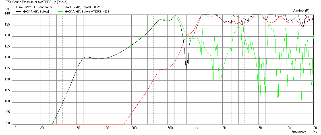
3 drivers without filters:

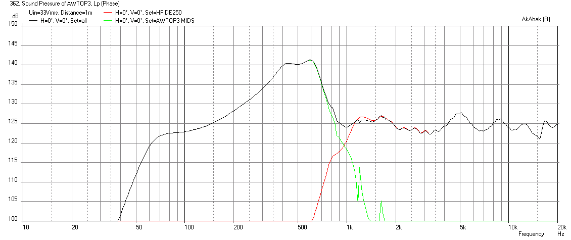
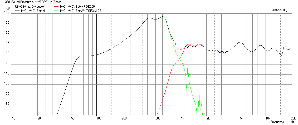
3 drivers with filters (-12dB/oct HPF at 54Hz and 24dB/oct XO at 700Hz) at xmax:
2 drivers without filters:
2 drivers with filters (-12dB/oct HPF at 54Hz and 24dB/oct XO at 700Hz) at xmax:
Port velocity at xmax for 2 drivers:

Port velocity at xmax for 3 drivers:

Velocity is kind of high at 35m/s - possible chuffing and port compression.
I swapped to the four ports to 3 inch SCH 40 PVC (3.042in dia) x 8 in long and this seemed to bring the tuning down to about 55Hz. This is the full horn with the extension. This is all 4pi space now, no reflections but diffraction is still turned on.
3 drivers without filters:
3 drivers with filters (-12dB/oct HPF at 54Hz and 24dB/oct XO at 700Hz) at xmax:
2 drivers without filters:
2 drivers with filters (-12dB/oct HPF at 54Hz and 24dB/oct XO at 700Hz) at xmax:
Port velocity at xmax for 2 drivers:
Port velocity at xmax for 3 drivers:
Velocity is kind of high at 35m/s - possible chuffing and port compression.
Attachments
-
 AWTOP3-2-drivers-Long-with-Filters-velocity.png27.9 KB · Views: 2,010
 -
 AWTOP3-2-drivers-Long-with-Filters.png40.5 KB · Views: 2,023
 -
 AWTOP3-2-drivers-Long-No-Filters.png45.3 KB · Views: 2,014
 -
 AWTOP3-3-drivers-Long-with-FILTERS.png40.9 KB · Views: 1,997
 -
 AWTOP3-3-drivers-Long-No-FILTERS.png44.4 KB · Views: 2,004
 -
 AWTOP3-3-drivers-Long-with-Filters-velocity.png28.1 KB · Views: 1,995
Last edited:
Looks like the 0.03 cubic foot (0.85L) specification for driver volume is the correct one, just reposting here that I measured 0.848L using rice.
I used my dead 10CL51 driver to do this- I am also happy to measure the rear volume as well if you like. No worries about screwing it up.
I'll be ready to build one of these as well, maybe I could try a quad 10CL version since I have four on hand
Also happy to whip up a CAD document as I'll be wanting that for reference during the build
Last edited:
- Status
- Not open for further replies.
- Home
- Loudspeakers
- Multi-Way
- Synergy Tripp 10"