

Looks like the master chamber might be about 15" tall for a compact version
Another view

Here I am seeing there might be a problem with the throat injection port? The driver rim intersects it
Last edited:
JG,
This is looking really promising - it might actually all fit! 15in tall is a very reasonable size box and I believe matches what you were looking for to sit on top of your sub. Can you provide a view with front horn removed to see what it looks like in compact mode? Also, can you put a master chamber around it and use the cad to get you the volume?
Thanks.
I have always had a hard time modeling a driver - how do you do it so fast? Even the electrical spade terminals!
Last edited:
JG,
This is looking really promising - it might actually all fit! 15in tall is a very reasonable size box and I believe matches what you were looking for to sit on top of your sub. Can you provide a view with front horn removed to see what it looks like in compact mode? Also, can you put a master chamber around it and use the cad to get you the volume?
Thanks.
Happy to hear you are liking where it is going. This is a way fun CAD file to work with.
The volume will take me some time because I still have to add material thickness, and I have to run to the market to get some food. Girl's gotta eat!
So, no issue with the throat injection port intersecting the rim? Will they have to be scooted out?
So, no issue with the throat injection port intersecting the rim? Will they have to be scooted out?
Hmmm.... If you used 3/4 in ply you may have room to cut an angled slot to fit inside the woofer cone area and still be as deep back as possible. The farther back it is, the better the bass extension will be from the front horn portion. I would move slots a little farther away from corner to give more material thickness. Note that top and bottom panels are larger rectangles to facilitate mounting drivers. You have it trimmed to a pyramid and that is fine for purposes of illustration. Alternatively, move that port downstream as far as you think necessary to clear the edge of the driver and tell me where the center of it is relative to the axial distance from throat (distance along axis of speaker). I will re-run model to to see if it looks ok - maybe just fine on which case that is the easy fix.
Thanks
Jenny,Here I am seeing there might be a problem with the throat injection port? The driver rim intersects it
Yes, some problems.
You must include the wood thickness in your CAD to determine how close the 10" can be placed to the HF driver mounting bracket, and also need to show a 1.4" exit in the bracket. The bracket will contain most of the round to rectangular transition radius into the horn.
The 10" exit ports should be mounted as close to the throat as possible, one driver on each of the four sides will work best for that goal.
The vertical dispersion on your design is to narrow for my needs, and the location of the driver on the bottom will interfere with a balanced tilting pole mount arrangement I plan to build in to my version, which may end up being a 2x10", rather than the original three 10" planned for the Tripp (pronounced "trippy").
I plan to use 1/2" material, with extensive bracing, the bass reflex ports will use the bracing, rather than tubes.
I am going back to the OP to correct some rather gross errors that have resulted in your interesting, but quite different cabinet design than the one I'll be building.
Art
Last edited:
Hi,
Amazingly quick progress.
This would probably not apply to Art's version, but w/ 4ea. 10" moved close to the transition of the secondary flare, and a little sidways, you might have enough room for 2ea/ 8" driver (which would have to have the backs sealed) w/ the ports close to the CD mounting board. Naturally that would change the whole thing into a 3-way, but it would optimize the conditions for the individual drivers.
Regards,
The vertical dispersion on your design is to narrow for my needs, and the location of the driver on the bottom will interfere with a balanced tilting pole mount arrangement I plan to build in to my version, which may end up being a 2x10", rather than the original three 10" planned for the Tripp (pronounced "trippy").
Your sketch called for 90deg x 35deg and that is how it came out. Maybe 90deg x 50deg?
Art- I matched the specs in xrk's drawing with this first go at it. More vertical dispersion would work for my needs, too, since the height of the drivers forces the master chamber to be at very minimum 15" anyway. It would seem to make sense that the main part of the horn could reach 15"-17" height as well (instead of 10"). That makes the horn (even minus the secondary add-on expansion) flush with the master chamber surrounding the drivers. To me, that does seem a better use of space on top of the added vertical dispersion.
If you want to throw some dimensions at me, I would be happy to draw it up. I have a feeling we are all after the same thing here 🙂
If you want to throw some dimensions at me, I would be happy to draw it up. I have a feeling we are all after the same thing here 🙂
Hi,
Amazingly quick progress.
This would probably not apply to Art's version, but w/ 4ea. 10" moved close to the transition of the secondary flare, and a little sidways, you might have enough room for 2ea/ 8" driver (which would have to have the backs sealed) w/ the ports close to the CD mounting board. Naturally that would change the whole thing into a 3-way, but it would optimize the conditions for the individual drivers.
Regards,
I'm not opposed to it at all...
*stares over at 2 lonely 8FE200's* 😉
Art- I matched the specs in xrk's drawing with this first go at it. More vertical dispersion would work for my needs, too, since the height of the drivers forces the master chamber to be at very minimum 15" anyway. It would seem to make sense that the main part of the horn could reach 15"-17" height as well (instead of 10"). That makes the horn (even minus the secondary add-on expansion) flush with the master chamber surrounding the drivers. To me, that does seem a better use of space on top of the added vertical dispersion.
If you want to throw some dimensions at me, I would be happy to draw it up. I have a feeling we are all after the same thing here 🙂
Ok so it looks like we are going into the Bwaslo spreadsheet to adjust vertical angle until the main section is 15in high? Whatever angle that ends up at. We still won't have enough room to mount drivers on the side panels without it bumping into the rim of the top or bottom mounted drivers. I will have to redo the AkAbak sim with the new geometry.
Jenny,If you want to throw some dimensions at me, I would be happy to draw it up. I have a feeling we are all after the same thing here 🙂
That would be great!
Could also use the 10" profile including the dust cap to aid in design of the filler ducting.
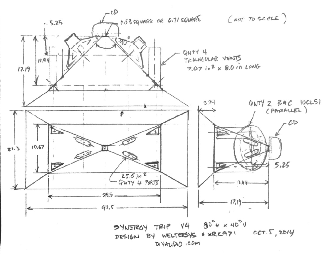
My preliminary design sketch side view is mislabled, it is actually about 44 degrees vertical, but I labeled it as 35. To make things worse, the top view is only 16.75" deep, but I labeled it 18.5".
I should have reviewed it all before posting, but was trying to mash it out quick, as my girlfriend was reminding me that I said I would be finished "in 10 minutes" 45 minutes later..
I'm in the process of a revision, as I need to drop down from the 30" width to 26.5" for my trailer pack to work. The SPL levels of 2x10" will be adequate for my needs, so dropping the 3x10" idea, which will simplify things, and reduce cost on a project I really have no need for, other than fun.
The exterior cabinet size using 1/2" plywood will now be 26.5 " wide x 19" deep x 11.42" tall, which result in about 50 liter (1.77 cubic feet) gross, about 40 liter net after drivers, ports, tilting stand mount, and bracing are deducted. As mentioned before, I'll be integrating the ports with bracing, after I run the numbers in Hornresp will post up the port plans.
Attached are the revised Bwaslo calculated figures, and a picture of the HF driver so you can understand why I used the .53 apex dimension, the horn effectively will extend to the HF diaphragm, about 40mm from the mounting bracket.
Art
Attachments


Hi Art- I like the idea of using bracing as the port. Looking forward to seeing the plans!
I don't quite understand what you mean by .53 apex and 40mm to the mounting bracket, can you explain that to me? Thank you!
I don't quite understand what you mean by .53 apex and 40mm to the mounting bracket, can you explain that to me? Thank you!
The ports will be four triangles in the corners, so will have minimal horn disruption, and will probably tune a bit lower than the area and length suggested in the Hornresp sims. I'll start with them at the suggested length for the 70Hz Fb, and cut them down if the tuning ends up low.Hi Art- I like the idea of using bracing as the port. Looking forward to seeing the plans!
I don't quite understand what you mean by .53 apex and 40mm to the mounting bracket, can you explain that to me? Thank you!
Looking down the throat of the Celestion CDX14-3050 you can see the .54" ring at the diaphragm due to the unusual phase plug combining a bullet shape with stepped annular rings. The cross sectional area basically should acoustically look like a continuation of the conical horn shape, more or less. The small difference between it as I have modeled it, or as a 1.4" truncation to the horn apex probably makes little difference in the sim, but it's the way I see it.
The sims look like an 800-900 Hz crossover is possible. The 2.65 ohm impedance is quite low for a pair of "8 ohm" drivers, a third driver would make many amps "cough".
Check my work, I'm rusty on Hornresp, could not remember how to check bass reflex port velocity, though the driver velocity was only 9meters a second, IIRC.
Art
Attachments


Last edited:
Are you saying your triangle ports are parallel to horn axis and located at the corners by a fillet board? Thus they won't be injecting perpendicularly to horn axis as I had it drawn earlier? I guess those are all variations up to the builder. I guess I should wait for a revised sketch before making another one for JG to make the 3d model. Do you agree there is no room to put a driver on the side walls?
The 0.54in dia you mention is the small silver ring inside the 1.4in dia aperture. The rest of the aperture still has sound because the solver ring is a phase plug right? Seems that it should still be 1.4in round or 1.00 in square and use a rasp to get the rounded parts. Not sure what compression driver JG plans on using 1.0 in dia or 1.4 in dia throat?
The 0.54in dia you mention is the small silver ring inside the 1.4in dia aperture. The rest of the aperture still has sound because the solver ring is a phase plug right? Seems that it should still be 1.4in round or 1.00 in square and use a rasp to get the rounded parts. Not sure what compression driver JG plans on using 1.0 in dia or 1.4 in dia throat?
1.4" for me!
The CD I will be using is a FaitalPRO HF144, ideally crossing over at around 900hz+. I won't have much use for the sub 100hz area so I'll be tuning a bit higher. Still unsure as to whether I'll be using 2 or 4 10CL51's, either. It looks like it will be MUCH easier to fit with just two. That way, the throat injection ports can stay as far up in there as possible.
The CD I will be using is a FaitalPRO HF144, ideally crossing over at around 900hz+. I won't have much use for the sub 100hz area so I'll be tuning a bit higher. Still unsure as to whether I'll be using 2 or 4 10CL51's, either. It looks like it will be MUCH easier to fit with just two. That way, the throat injection ports can stay as far up in there as possible.
The ports will be four triangles in the corners, so will have minimal horn disruption, and will probably tune a bit lower than the area and length suggested in the Hornresp sims. I'll start with them at the suggested length for the 70Hz Fb, and cut them down if the tuning ends up low.
Looking down the throat of the Celestion CDX14-3050 you can see the .54" ring at the diaphragm due to the unusual phase plug combining a bullet shape with stepped annular rings. The cross sectional area basically should acoustically look like a continuation of the conical horn shape, more or less. The small difference between it as I have modeled it, or as a 1.4" truncation to the horn apex probably makes little difference in the sim, but it's the way I see it.
The sims look like an 800-900 Hz crossover is possible. The 2.65 ohm impedance is quite low for a pair of "8 ohm" drivers, a third driver would make many amps "cough".
Check my work, I'm rusty on Hornresp, could not remember how to check bass reflex port velocity, though the driver velocity was only 9meters a second, IIRC.
Art
I am trying to work through your settings here. Is it correct that you are using the equivalent of a 5.7in dia injection port (per driver) at 5.25in from the throat? I am using qnty 4 3.0 dia x 8.0in long BR ducts in a 40 liter enclosure. With this geometry, I am getting an Akabak sim that closely matches yours. However, I feel that the upper bandwidth is too low for a XO at 800 to 900Hz - there is a steep fall off at 750Hz. I put the 4 ports at 1.5in away (axially) from the S4 plane assuming a 3in "diameter" duct - even with a triangle port, distance is about the same.
Here is the response without any filters:
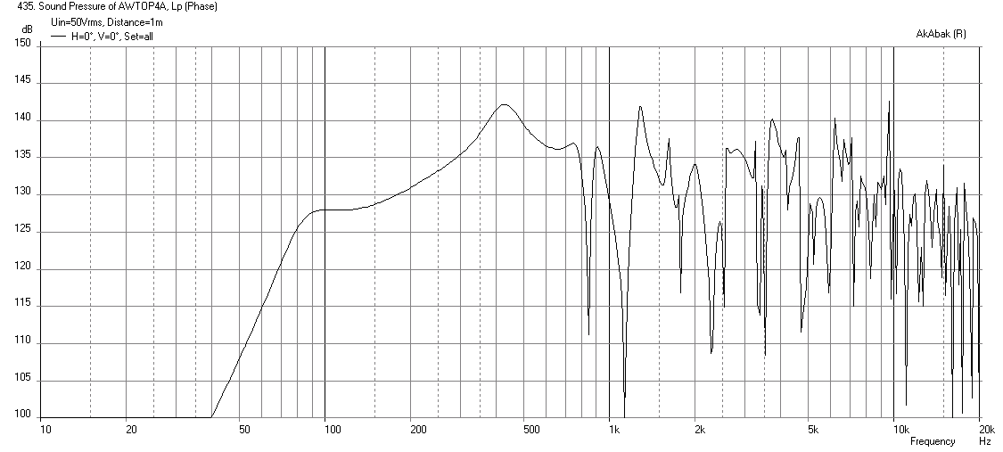
Here is the response with 75Hz HPF (-12dB/oct) and 600Hz LPF (-24dB/oct):

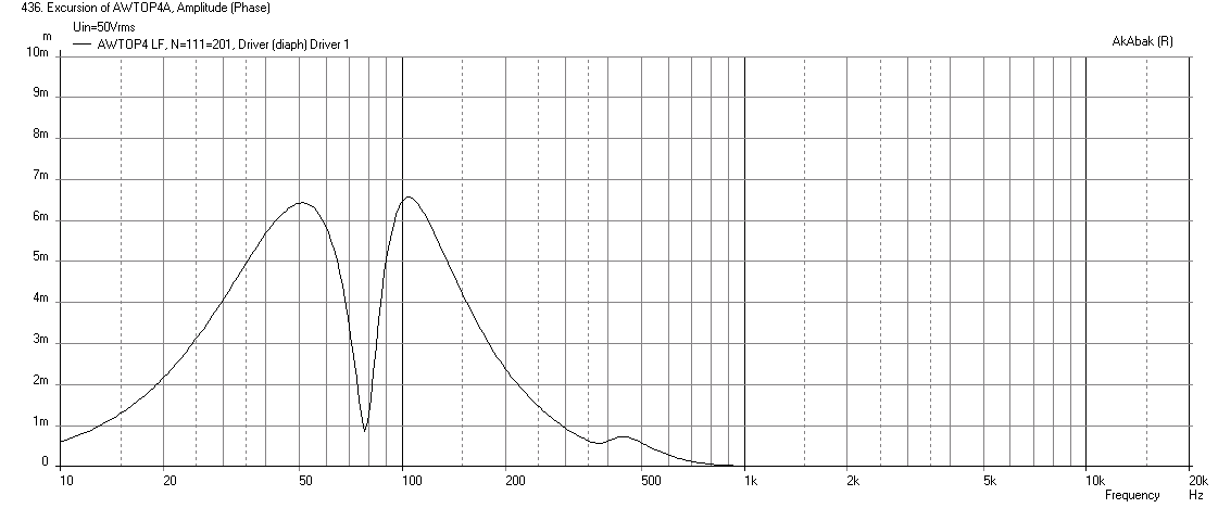
Here is corresponding cone displacement:
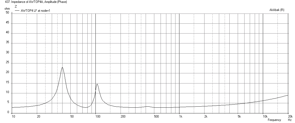
Here is Impedance showing fb is about 74Hz:
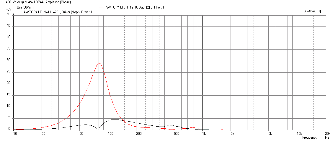
Here is the port and cone velocity - with this setting the port velocity is about 30m/s at xmax - not sure if that is acceptable to you:
Here is the electrical power input at xmax, well above the AES rating, but maybe that is fine given the crest factors you use:
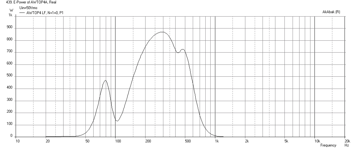
I tried reducing the volume of the driver cone chamber and that doesn't increase freq of the steep drop off at 750Hz much - it just increases the junk that comes out above it so the LPF will not be able to cut it all out. I think you need a shallower Horiz dispersion angle and a longer horn to get a longer path for the bass injection ports to move that up. Something along the lines of a 50x50 synergy. Otherwise need to use a higher fs mid driver like a 5in with fs around 400Hz to 500Hz, and go with a 3-way. Which we are trying to avoid I believe. Interestingly, the design from post 15 seemed to have a smoother falloff even though it was at 600Hz or so.
So my question is this: is it so bad to have a 35 deg vertical dispersion angle as designed previously and already drawn up by JG? I think a narrow horn (in one dim or the other) helps in a synergy configuration. I have seen this observation mentioned before by others. It also provides a flatter profile which I think JG was looking for. I think it may be an easy change to simply make the last design a 2-driver by going with drivers mounted on side panels to allow your pole mounting and to keep costs down. This way JG has enough drivers to make a stereo pair. I am not sure there is much benefit to going from 35 deg to 40 deg vertical unless you plan to fly this high up and aim down. But used at 60 to 72 in high from the back of a truck or pole mount, 35 deg seems OK. The "squashed" form factor looks different from other synergies out there and is very cool, IMO. But then again, I think your main constraint was that the main box is 26.5in to fit with your other boxes for transport? That narrowness changed the horn response and is making for a difficult 2-way XO at 800-900Hz.
Attachments
-
 AWtop4-with-Filters-Electrical-Power.png37.6 KB · Views: 1,128
 -
 AWtop4-with-Filters-Velocity.png36.2 KB · Views: 1,149
 -
 AWtop4-with-Filters-Impedance.png34.2 KB · Views: 1,128
 -
 AWtop4-with-Filters-Displ.png37.9 KB · Views: 1,128
 -
 AWtop4-with-Filters-Freq-1m.png38.1 KB · Views: 1,383
 -
 AWtop4-No-Filters-Freq-1m.png45.1 KB · Views: 1,654
Last edited:

2nd look at 8FE200
I have a very similar shaped horn simulation going on using 8FE200. I substituted your horn dimensions for mine and with that sole change the "steep dropoff" moved out to 900 Hz. The top sim is in 4pi space. The lower 2 are in 2pi space for use in home and show before and after equalization using HR's filter wizard. It doesn't look like enough output for Art, as was said, but should be good for JG's use.
BTW: 450 mL of water fills the 8FE200's cone.
Attachments

- Status
- Not open for further replies.
- Home
- Loudspeakers
- Multi-Way
- Synergy Tripp 10"