S1 filled vs not filled
Also just discovered ability to model filling horn with absorption. I played with that and it cleans up the response even more, as you can see on the attachment. I have no idea why the SPL in my sim is so much lower than in XRK's (?)
I wish I could move as fast as you are going but I don't have the experience to know where reality will be better than predicted by HR and its lots easier for me to find time in front of the computer than out in the garage sawing wood.
These posts of mine are just part of my learning process. I'm seeking confirmation/explanation of the apparent discrepancy or problem that I see. I'm certainly not trying to teach anyone other than myself. thanks for your response
I only just noticed that (throat velocity) feature myself - wasn't sure when it was added. Last year people were posting you had to go to Akabak for that info.Jack,
Yes, I don't have the current version of Hornresp, but it can look at particle velocity in the offset horn throat. Your sim looks more encouraging than mine, and I will be experimenting with smaller offset entrance ports and various "phase plugs".
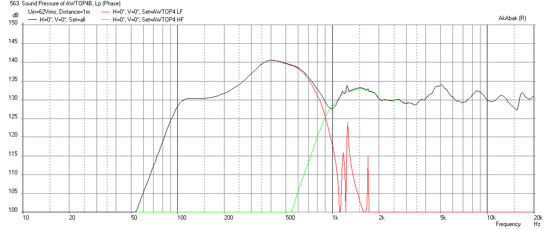
My experience is the sharp pipe resonances Hornresp predicts end up being half the level or so, and four triangle ports may be less "pipey" than the single round one Hornresp uses. We'll soon see, ordering drivers this morning, probably will have the cabinets built and HF driver tests done by the time the 10" arrive.
Art
Also just discovered ability to model filling horn with absorption. I played with that and it cleans up the response even more, as you can see on the attachment. I have no idea why the SPL in my sim is so much lower than in XRK's (?)
I wish I could move as fast as you are going but I don't have the experience to know where reality will be better than predicted by HR and its lots easier for me to find time in front of the computer than out in the garage sawing wood.
These posts of mine are just part of my learning process. I'm seeking confirmation/explanation of the apparent discrepancy or problem that I see. I'm certainly not trying to teach anyone other than myself. thanks for your response
Attachments

I have never worked with Akabak, so don't know why xrk97's sims look so different from the Hornresp sims, though he is using smaller offset ports, which increase upper response.I
Also just discovered ability to model filling horn with absorption. I played with that and it cleans up the response even more, as you can see on the attachment. I have no idea why the SPL in my sim is so much lower than in XRK's (?)
Filling S1 with absorption would kill the HF response of the HF driver which shares the horn, so forget about that feature when modeling a Synergy 😉.
I have never worked with Akabak, so don't know why xrk97's sims look so different from the Hornresp sims, though he is using smaller offset ports, which increase upper response.
I'm planning to cross to external 18" woofers outside the (corner) horn at about 200 Hz and I want that increased upper response to be able to use a 1"throat driver crossed at 1Khz or higher.
So I want to use smaller ports also. How would I choose port size? Apply a maximum port particle velocity limit at reduced velocities due to crossover HPF? What limit would you suggest?
[QUOTE
Filling S1 with absorption would kill the HF response of the HF driver which shares the horn, so forget about that feature when modeling a Synergy 😉.[/QUOTE]
whoops!
Thanks
I have no idea why the SPL in my sim is so much lower than in XRK's (?)
Please show me which plot and what freq region you are talking about for the discrepancy. Are you modeling 2, 3, or 4 drivers? How do you have them connected? 2 and 3 drivers are all in parallel so sensitivity at same 2.83v will be higher as impedance drops with more drivers. I calculate max SPL by setting drive voltage to hit xmax of 6.5mm.
So I want to use smaller ports also. How would I choose port size? Apply a maximum port particle velocity limit at reduced velocities due to crossover HPF? What limit would you suggest?
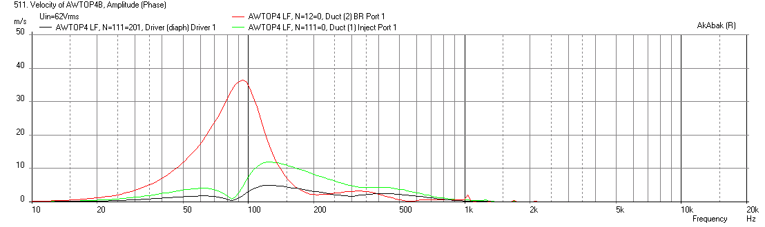
Look at overall response shape and adjust port size to get as smooth as possible, check velocity at ports to make sure less than say 20m/s to prevent chuffing and port compression. I think some people may even say 30m/s sec is OK. In looking at this more carefully, I see that Weltersys' use of 5.25in dia ports gives a max velocity of 12m/s at xmax for 3 drivers while a 3in dia port gives unacceptable 35m/s velocity. The BR ports at 3in will also have high velocities so it may make sense to to with longer 4in dia equiv CSA but longer ports.
Edit - checking effect of BR port dia on velocity and freq response.
Nothing is simple... Here is the freq response and port velocities for 5.25in dia offset ports with 3in dia BR ports - BR port velocity is very high at xmax but response is smooth:
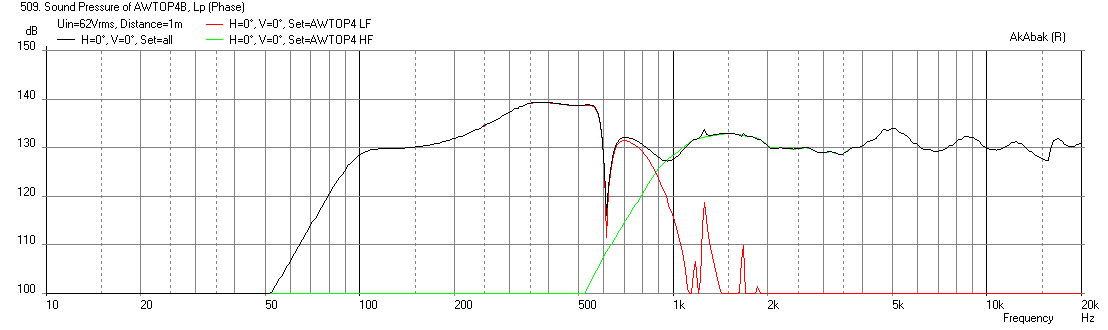
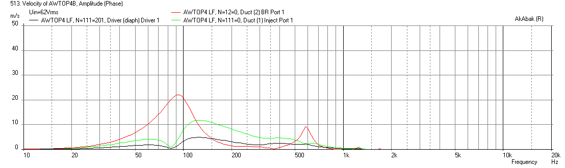
Here is freq response and port velocities for 5.25in dia offset ports with 4in dia BR ports - now velocities look reasonable but the freq response has a big sharp dip - not very good and really messes with the XO point. I am not sure what is causing this, but it may be additional out-of-phase resonances from BR port interfering with main output causing cancellation dip? I would take chuffing at xmax (peak excursions) over a nasty dip like this:
Attachments


Last edited:
I've posted the HR input parameters as well as SPL for my sim back just 3 or 4 posts. 2 drivers in parallel. the SPL plots are with max excursion of 6 mm.
I would ask the same questions of you. In fact I'd love to see your script as I'm sure I could learn a lot from it.
I'm getting only 115 db at 150 hz in 4 pi space while I think the last sim you posted was >125 db
I would ask the same questions of you. In fact I'd love to see your script as I'm sure I could learn a lot from it.
I'm getting only 115 db at 150 hz in 4 pi space while I think the last sim you posted was >125 db
I'm getting only 115 db at 150 hz in 4 pi space while I think the last sim you posted was >125 db
I am not a HR expert, but I recall sometimes there is a discrepency in SPL and it has to do with whether you are looking at power or pressure. Tb46 can probably answer this. I know that Akabak's calcs of SPL (pressure and freq location) for the main bass "knee" region is very accurate as I have seen in measurements of speakers I have designed.
For 2 drivers in parallel, I get 125dB at 150Hz for 6mm displacement with 54.5 volts.
That rings a bell. In fact, I think I might have provided the same tip to someone else a few months ago. Now that I think about it, I've actually exported an akabak script from HR and got matching output, after a short tussle. But HR output matches Akabak's acoustic pressure output, which is harder to call up on the Akabak screen. Earlier this year, HR retitled its frequency response charts "Acoustic Pressure". That should have been a clue to me.
I think I need more coffee🙂
I think I need more coffee🙂
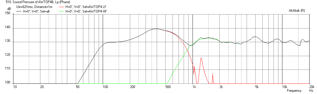
3 drivers, SHORT horn, qnty 8 x 2.047in dia (2in SCH 40 PVC) ports
You can use qnty 8 x 2in PVC ports or make equivalent 3.29in2 triangular ports that are 5.5in long to get this response at 6.5mm xmax (assume 40 liter rear chamber).
You can use qnty 8 x 2in PVC ports or make equivalent 3.29in2 triangular ports that are 5.5in long to get this response at 6.5mm xmax (assume 40 liter rear chamber).
Attachments

thanks for the graphs you added to post 84
So if I had an LR2 HPF at 150 Hz, then velocity, which seems to scale linearly with the output level, would be halved and I could arguably go with 1/2 size or even smaller holes. But changing hole size would change the FR and so all the throat port parameters would have to be re-examined and tuned.
So if I had an LR2 HPF at 150 Hz, then velocity, which seems to scale linearly with the output level, would be halved and I could arguably go with 1/2 size or even smaller holes. But changing hole size would change the FR and so all the throat port parameters would have to be re-examined and tuned.
That rings a bell. In fact, I think I might have provided the same tip to someone else a few months ago. Now that I think about it, I've actually exported an akabak script from HR and got matching output, after a short tussle. But HR output matches Akabak's acoustic pressure output, which is harder to call up on the Akabak screen. Earlier this year, HR retitled its frequency response charts "Acoustic Pressure". That should have been a clue to me.
I think I need more coffee🙂
Arghh! Definitely need more coffee - its "Acoustic Power" from HR that matches Akabak acoustic power.
I am not sure why the default in HR is not what one measures as the common "Freq Response" curve of SPL (dB) vs Freq (Hz). That is what AkAbak plots wen I click the calculate SPL button.
Then you should be looking at 6.5" or 8" mid drivers (which can go higher), the 10" are not going to cut it much above 700 Hz.I'm planning to cross to external 18" woofers outside the (corner) horn at about 200 Hz and I want that increased upper response to be able to use a 1"throat driver crossed at 1Khz or higher.
Then again, a 1" at 700 Hz can get pretty loud, but it won't get near as loud as the 10s" before the diaphragm hammers the phase plug, creating a very unpleasant sound, and will destroy aluminum quite rapidly.
Legis,
4)How did you measure? The reason for the edge ports is to affect the HF the least.
5) Perhaps you could illustrate what you are explaining, I don't quite "see" it.
6) Measure various compression drivers without a horn, you will notice differences in their "flat wave front". Your use of a JBL 2450, with it's built in conical horn throat, is quite different than the drivers typically used on Synergies.
Art
4) With the mic inside the horn, either at the center of side where the injection ports are routed, or at the corner. Midwoofer injection ports were closed with a tape during the measurement. The difference was quite small with my horn's dimensions, comp driver (2446J) and the measurement distance (~9cm from the throat, pretty close where my round injection ports start).
Edge measurement is the blue one.
An externally hosted image should be here but it was not working when we last tested it.
5) I basically mean ports like I did, one big round port that covers the whole side. If the benefits outweight the possible downsides of doing such ports.
6) How do you measure if the comp driver has flat wave front, from directivity? The edge diffraction should be kept under control when measuring comps without any horn.
Basically don't all "phase coherent" phasing plugs, that make the path lenght from different parts of the dome/ring constant at the end of the phasing plug (to get the most HF extension) generate flat wave front at the end of the phasing plug (in some sense, at HF at least)? After this the wave front starts to expand and curve into a more spherical wave front, at least in conical expansion horns(/oblate spheroids) to my understanding. But at the throat and close to it the wave front might not be very spherical?
Last edited:
Hi Legis,
Glad you could join us here, another synergy party. 🙂
The bump as you noticed is rather high and will require about 15dB cut to level out with the bass from the ports. It is not really because of the compression ratio - I played with it to make it even bigger than physically possible at the location on the horn wall. What you see there is the horn gain for the appropriate bandwidth. Note that this is a very short horn with a main conical expansion of 13in so that main gain is up past 500Hz or so. It is not from a compression peak in a bandpass port. A lot of level cut has to be applied to the CD as well to get it lower to match the bass. If this were run all out the system is capable of 140dB as a 2-way from 500Hz up. If we threw maybe four really big 15in 100dB woofers at it for a 3-way that may help to even things out but still not horn loading really with such a short length. With your 1m long (39in) horn with 11cm ports and dual 15in drivers you were able to get a pretty flat response to below 100Hz. I am seeing in the sims that you can probably get your top end higher with a volume plug inside the cone. You have a CD that can reach 500Hz but sometimes getting the electrical XO point higher may have some benefits to keep it out of the phase changing acoustical XO region. Although in your case I think you run it full range with exception of high pass filter?
I also suspect the response of my synergies could be made go flat higher with smaller front chamber, but by how much based on your sims? You can also send me pm if you wish so this thread does not get corrupted 🙂. Yes, the comp has high pass only, otherwise full range.
I also suspect the response of my synergies could be made go flat higher with smaller front chamber, but by how much based on your sims? You can also send me pm if you wish so this thread does not get corrupted
Or we can discuss it back in the other thread: http://www.diyaudio.com/forums/subwoofers/258706-study-dipole-cardioid-bass-horn.html
I will see what I can do...
1) Your narrow horn is nearly symmetrical, IIRC, so throat pressures appear to be quite even in the corners vs. the center of sides where you placed the injection ports.1) With the mic inside the horn, either at the center of side where the injection ports are routed, or at the corner.
2) I basically mean ports like I did, one big round port that covers the whole side. If the benefits outweight the possible downsides of doing such ports.
3) How do you measure if the comp driver has flat wave front, from directivity?
4)Basically don't all "phase coherent" phasing plugs, that make the path lenght from different parts of the dome/ring constant at the end of the phasing plug (to get the most HF extension) generate flat wave front at the end of the phasing plug (in some sense, at HF at least)?
5)After this the wave front starts to expand and curve into a more spherical wave front, at least in conical expansion horns(/oblate spheroids) to my understanding. But at the throat and close to it the wave front might not be very spherical?
My SynTripP horn will have an 86.5 x 36 pattern, so I'd expect to see a bit less pressure off to the wide sides, as that is what conical horns measure like, the diagonal being wider, SPL is further down in that plane.
2)Your measurements using a JBL 2450 seem to show little problem with the big round port located near the throat, but so far I haven't seen any polar charts at a distance from the horn, measurements across the mouth are within the horn "bubble", and may not represent what happens outside the "bubble".
3) My quick and dirty tests have just confirmed that the output of the compression driver is roughly spherical, other than the narrowing in high frequencies of the conical section used on old style drivers like the JBL 2420, 2440, 2450, etc.
4)If the wave was planar, it would "beam" at high frequencies, rather than filling the horn.
5) Might, might not, there are a lot of different phase plug designs designed to work with different horn geometries. Since I won't be designing drivers, I just try to make whatever horn work with the driver chosen.
Revision 3: A smaller cabinet
Revision 3:
A smaller cabinet, with no loss in output, but some loss in horizontal pattern control, about 284 Hz compared to the previous version at 226 Hz. Having fourteen cabinets of this size presently, decided the larger cabinet just didn't fit well with my needs.
The main cabinet is 26.5" x 15" deep by 11.25" tall, which results in approximately 31 liter net volume after subtracting horn, drivers, tilt stand, and port volume. The cabinet uses four bass reflex ports, each approximately 11.5" (29.2cm) long with approximately 7.5 square inch (48cm2) exit, using the 10" driver baffle board as one vertical side.
The secondary portion of the horn (still under consideration) will be approximately 34" wide x 15.5" tall x 2" deep, and will use turnbuckles to attach to the handles of the main cabinet.
Art
Attachments


I think this design is very close to what I drew a few pages back. Can you show the Bwaslo spreadsheet inputs again for this design if it has changed? With a narrow aspect ratio box are you worried about pattern flip?
Pattern flip is unavoidable without a vertical dimension equal to the horizontal, so I don't worry too much considering I won't lug around a 5 foot (or whatever depth a 36 degree vertical Synergy horn with control to 284 Hz would require) deep horn.Can you show the Bwaslo spreadsheet inputs again for this design if it has changed? With a narrow aspect ratio box are you worried about pattern flip?
IIRC, this horn has control good to around 1400 Hz vertical, enough to keep from tearing off the heads of people close if adequately elevated.
Bwaslow spreadsheet:
Attachments

- Status
- Not open for further replies.
- Home
- Loudspeakers
- Multi-Way
- Synergy Tripp 10"