Thanks for that. I actually had a similar design with two 8FE200's that I did earlier for JG that had good response out to 1khz too. It was a 50x50deg design.
http://www.diyaudio.com/forums/subwoofers/262305-faitalpro-15hp1060-vs-3015lf-tapped-horn-39.html#post4076821
http://www.diyaudio.com/forums/subwoofers/262305-faitalpro-15hp1060-vs-3015lf-tapped-horn-39.html#post4076821
Here is the rough plan based on Weltersys data from above post.
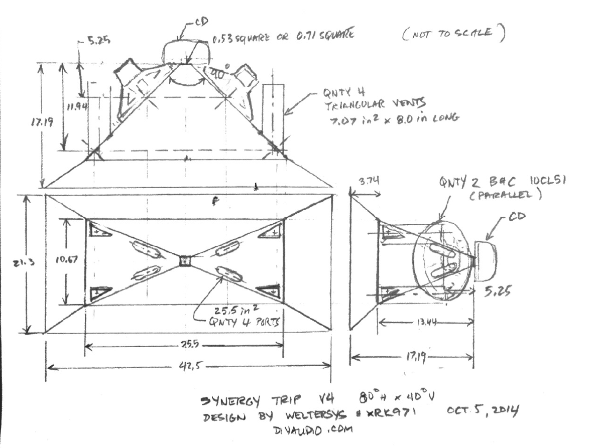
Typo in drawing - actually 80 x 40 deg.
I'm so confused.
Hi Art,
Here is some stuff I noticed:
In Post #52 the text reads: "...cabinet size using 1/2" plywood will now be 26.5 " wide x 19" deep x 11.42" tall..."
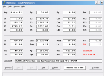
Your attached bwaslo spreadsheet screenprint (same post) says: width L=42.530 - height J=21.109 - depth M=17.410. These larger dimensions are reflected in Post #59 by xrk971 in his V4 plan.
So, which size are you shooting for?
I like the decision to go w/ 2ea. 10" and a 1ea. CD for your application. Lighter, smaller ....
JG has the cone volume for the 10CL51 @ ~850cc, in Hornresp that needs to be doubled for two speakers plus the volume of any volume added for a spacer ring plus the volume for cutting the frustums on the front ports, or you need to install some kind of displacement reducing cone.
In Hornresp L12 should be the distance from the CD cone to the 10" injection ports. As the portion of L12 from the throat inside the CD to the CD exit is @ a different taper than from the CD throat exit to the 10" injection ports, maybe L12 should be exponential instead of conical. That may affect the high frequency corner. And the area of the throat chamber (10") has to be multiplied by 2 to reflect 2 drivers.
Regards,
Hi Art,
Here is some stuff I noticed:
In Post #52 the text reads: "...cabinet size using 1/2" plywood will now be 26.5 " wide x 19" deep x 11.42" tall..."
Your attached bwaslo spreadsheet screenprint (same post) says: width L=42.530 - height J=21.109 - depth M=17.410. These larger dimensions are reflected in Post #59 by xrk971 in his V4 plan.
So, which size are you shooting for?
I like the decision to go w/ 2ea. 10" and a 1ea. CD for your application. Lighter, smaller ....
JG has the cone volume for the 10CL51 @ ~850cc, in Hornresp that needs to be doubled for two speakers plus the volume of any volume added for a spacer ring plus the volume for cutting the frustums on the front ports, or you need to install some kind of displacement reducing cone.
In Hornresp L12 should be the distance from the CD cone to the 10" injection ports. As the portion of L12 from the throat inside the CD to the CD exit is @ a different taper than from the CD throat exit to the 10" injection ports, maybe L12 should be exponential instead of conical. That may affect the high frequency corner. And the area of the throat chamber (10") has to be multiplied by 2 to reflect 2 drivers.
Regards,
Last edited:
Your attached bwaslo spreadsheet screenprint (same post) says: width L=42.530 - height J=21.109 - depth M=17.410. These larger dimensions are reflected in Post #59 by xrk971 in his V4 plan.
I think the width Weltersys is referring to is the first expansion box. The big width is with the secondary expansion attached to the main smaller box.
1) My port sizes were way off (I can't think in metric for beans), revisions below. I don't have a lot of confidence in the simulation (for instance the BR port combined output makes one of the upper sharp peaks, and that will be eliminated by placement and fill material) and the actual shape and volume reducers will result in unpredicted differences, I'll be experimenting with the actual transducers and horn to find the best combination.1)I am trying to work through your settings here. Is it correct that you are using the equivalent of a 5.7in dia injection port (per driver) at 5.25in from the throat?
2) I think you need a shallower Horiz dispersion angle and a longer horn to get a longer path for the bass injection ports to move that up.
3)So my question is this: is it so bad to have a 35 deg vertical dispersion angle as designed previously and already drawn up by JG? I am not sure there is much benefit to going from 35 deg to 40 deg vertical unless you plan to fly this high up and aim down.
2) The 85x40 pattern is as narrow dispersion in either direction for my needs, more narrow horizontal would require two cabinets per side, more narrow vertical would result in too high a frequency loss of pattern control. The horn length is fixed by the width, 26.5 external is as large as my trailer will allow with the rest of the equipment.
Jenny's application is quite different than mine, so my design may not fit either her aesthetic or other requirements.
The rough draft below used the full side panel length so I could more accurately figure the port location, so makes the vertical angle look more narrow than it is. If you look at the screen from 42.5 degrees off axis to the right, it looks correct
") .
.Thanks for the help!
Art
Attachments
Last edited:
Hi xrk971,
It all depends on how much secondary flare is really necessary. Some of Danley's designs look a lot like the bwaslo spreadsheet, and some have very little secondary flare. Ultimately Art and JG will have to build, and measure. Similar situation w/ pattern flip, here an equal horizontal and vertical expansion seem clearly superior, again: build, and measure.
Regards,
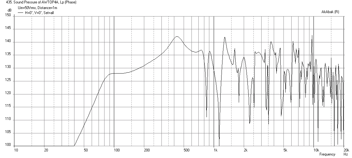
Pipe resonance problem?
Hi Art:
Are you using an old version of HR? Sometime in the last few months, the SPL graph labels were changed to "Acoustic Power". There are several new features I'm sure you'll like - an equalizer in the filter wizard and ability to look at particle velocity in offset horn throat.
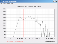
Running your simulation model from a couple posts back in the latest HR, I get a prettier picture but the port output screen shows the pipe resonance in the middle of the passband is only down 10 db.
Jack
Hi Art:
Are you using an old version of HR? Sometime in the last few months, the SPL graph labels were changed to "Acoustic Power". There are several new features I'm sure you'll like - an equalizer in the filter wizard and ability to look at particle velocity in offset horn throat.
Running your simulation model from a couple posts back in the latest HR, I get a prettier picture but the port output screen shows the pipe resonance in the middle of the passband is only down 10 db.
Jack
Attachments
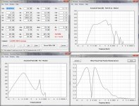
If you look at the screen from 42.5 degrees off axis to the right, it looks correct
Now this is a mathematical way to view things I can get behind
I took a quick break to work on some car stuff, ready to do some CADing whenever you guys are ready!
I would also love to have 90 degree dispersion- I'm only planning on running one of these boxes without the "expansion pack". The only thing I worry about if I just follow Art's needs is if the peak SPL will be severely underpowered compared to my sub- which is 130dB capable. Perhaps a higher tuning will be able to bring some of that back, I guess it is time to run some sims for my scenario
Interesting thread.
Simulated response could be made more straight before the acoutical cut off? Even for DSP systems one could (imo should) try to obtain smooth response pre-eq since adding extra eq-algorithms to DSP's data-queue isn't totally harmless and does not come without "bit losses".
What is the compression ratio of injection ports for the mids? Perhaps bigger ports would make the response flatter? This would propably need some redesign or to utilize the space also at the center of the walls and not just the edges.
------------
.... As a side trail, I have not been able to measure lower total acoustical pressure at the edges of quadrilateral conical horn. If there is no difference in pressure at the edges, does it make a difference to place the injection ports to the edges? I speculate that the ports will act as nearly the same acoustical impedance path regardless where the ports are placed (at centrer or the edges at same distance) at least with 1,4-2" comp drivers.
In space constrained projects, maybe bigger benefit would be gained by making the ports larger by utilizing also the area at the center of the side besides the edges. Trade minor (or none) HF response degradation to better/flatter MF response?
If there should be a difference in acoutical pressure at the edges with flat wave front (like all comp drivers output because of the phasing plug), how big the difference should be in theory, anybody have a clue?
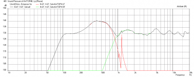
Here is the response without any filters:
Here is the response with 75Hz HPF (-12dB/oct) and 600Hz LPF (-24dB/oct):

Simulated response could be made more straight before the acoutical cut off? Even for DSP systems one could (imo should) try to obtain smooth response pre-eq since adding extra eq-algorithms to DSP's data-queue isn't totally harmless and does not come without "bit losses".
What is the compression ratio of injection ports for the mids? Perhaps bigger ports would make the response flatter? This would propably need some redesign or to utilize the space also at the center of the walls and not just the edges.
------------
.... As a side trail, I have not been able to measure lower total acoustical pressure at the edges of quadrilateral conical horn. If there is no difference in pressure at the edges, does it make a difference to place the injection ports to the edges? I speculate that the ports will act as nearly the same acoustical impedance path regardless where the ports are placed (at centrer or the edges at same distance) at least with 1,4-2" comp drivers.
In space constrained projects, maybe bigger benefit would be gained by making the ports larger by utilizing also the area at the center of the side besides the edges. Trade minor (or none) HF response degradation to better/flatter MF response?
If there should be a difference in acoutical pressure at the edges with flat wave front (like all comp drivers output because of the phasing plug), how big the difference should be in theory, anybody have a clue?
Last edited:
Hi Legis,
Glad you could join us here, another synergy party.
The bump as you noticed is rather high and will require about 15dB cut to level out with the bass from the ports. It is not really because of the compression ratio - I played with it to make it even bigger than physically possible at the location on the horn wall. What you see there is the horn gain for the appropriate bandwidth. Note that this is a very short horn with a main conical expansion of 13in so that main gain is up past 500Hz or so. It is not from a compression peak in a bandpass port. A lot of level cut has to be applied to the CD as well to get it lower to match the bass. If this were run all out the system is capable of 140dB as a 2-way from 500Hz up. If we threw maybe four really big 15in 100dB woofers at it for a 3-way that may help to even things out but still not horn loading really with such a short length. With your 1m long (39in) horn with 11cm ports and dual 15in drivers you were able to get a pretty flat response to below 100Hz. I am seeing in the sims that you can probably get your top end higher with a volume plug inside the cone. You have a CD that can reach 500Hz but sometimes getting the electrical XO point higher may have some benefits to keep it out of the phase changing acoustical XO region. Although in your case I think you run it full range with exception of high pass filter?
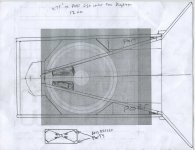
80 deg H x 40 deg V4 with 3 drivers - SHORT version
JG,
With the front extension removed, this horn is downright petite with outside cabinet size of 23.5in W x 13.5in H x 18.5in deep. Assuming your 3d model shows that 3 drivers can fit (third on top panel), and trimming the 3in dia ports down to 6.5in long, making the woofer injection ports equivalent to 3in dia holes for each driver (with woofer volume fillers to cut 850 cc to 450cc), and using a -12dB/oct HPF @98Hz and a -24dB/oct XO @700Hz, you get this response which is 130dB SPL at 62volts and flat to 108 Hz (-3dB point is 94Hz):
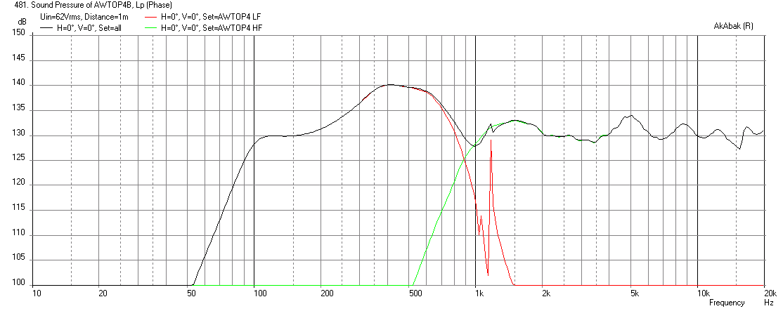
I think this should be a good match for your sub... let me know if this looks OK and I will run the rest of the sims for impedance, power, velocity, etc. The model is for the B&C DE250 compression driver, if you have a larger 1.4incher, you can probably cross lower and get a smoother response. As is, it looks like a basic 1in CD can work with this configuration, although not ideal.
JG,
With the front extension removed, this horn is downright petite with outside cabinet size of 23.5in W x 13.5in H x 18.5in deep. Assuming your 3d model shows that 3 drivers can fit (third on top panel), and trimming the 3in dia ports down to 6.5in long, making the woofer injection ports equivalent to 3in dia holes for each driver (with woofer volume fillers to cut 850 cc to 450cc), and using a -12dB/oct HPF @98Hz and a -24dB/oct XO @700Hz, you get this response which is 130dB SPL at 62volts and flat to 108 Hz (-3dB point is 94Hz):
I think this should be a good match for your sub... let me know if this looks OK and I will run the rest of the sims for impedance, power, velocity, etc. The model is for the B&C DE250 compression driver, if you have a larger 1.4incher, you can probably cross lower and get a smoother response. As is, it looks like a basic 1in CD can work with this configuration, although not ideal.
Attachments
Last edited:
Jack,Hi Art:
Are you using an old version of HR?
Running your simulation model from a couple posts back in the latest HR, I get a prettier picture but the port output screen shows the pipe resonance in the middle of the passband is only down 10 db.
Jack
Yes, I don't have the current version of Hornresp, but it can look at particle velocity in the offset horn throat. Your sim looks more encouraging than mine, and I will be experimenting with smaller offset entrance ports and various "phase plugs".
My experience is the sharp pipe resonances Hornresp predicts end up being half the level or so, and four triangle ports may be less "pipey" than the single round one Hornresp uses. We'll soon see, ordering drivers this morning, probably will have the cabinets built and HF driver tests done by the time the 10" arrive.
Art
Jenny,I would also love to have 90 degree dispersion- I'm only planning on running one of these boxes without the "expansion pack". The only thing I worry about if I just follow Art's needs is if the peak SPL will be severely underpowered compared to my sub- which is 130dB capable.
Your sub probably won't quite do 130 dB,(have you measured it yet?) but even if it does, IIRC much of the music you play requires 10-20 dB more LF than the >100 Hz range.
Art
Legis,1)Simulated response could be made more straight before the acoutical cut off?
2)What is the compression ratio of injection ports for the mids?
3)Perhaps bigger ports would make the response flatter?
4) As a side trail, I have not been able to measure lower total acoustical pressure at the edges of quadrilateral conical horn. If there is no difference in pressure at the edges, does it make a difference to place the injection ports to the edges?
5)In space constrained projects, maybe bigger benefit would be gained by making the ports larger by utilizing also the area at the center of the side besides the edges. Trade minor (or none) HF response degradation to better/flatter MF response?
6)If there should be a difference in acoutical pressure at the edges with flat wave front (like all comp drivers output because of the phasing plug), how big the difference should be in theory, anybody have a clue?
1) Hornresp appears to predict a much flatter response than Akabak, but even if the response falls between the two, the reduction of midrange is no problem with DSP, the reduction will flatten phase too.
2)Two 10"Sd is 640/73Apt, 8.8 to one. Seems on the high side to me but velocity at 8meters per second would indicate even a higher ratio may work, actual tests will tell.
3) They did in the sim, my first attempt was almost flat, but then xrk971 pointed out they would take up half the throat
.4)How did you measure? The reason for the edge ports is to affect the HF the least.
5) Perhaps you could illustrate what you are explaining, I don't quite "see" it.
6) Measure various compression drivers without a horn, you will notice differences in their "flat wave front". Your use of a JBL 2450, with it's built in conical horn throat, is quite different than the drivers typically used on Synergies.
Art
- Status
- This old topic is closed. If you want to reopen this topic, contact a moderator using the "Report Post" button.
- Home
- Loudspeakers
- Multi-Way
- Synergy Tripp 10"