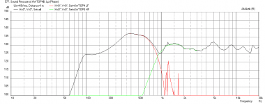
its "Acoustic Power" from HR that matches Akabak acoustic power.
Correct.
Hornresp and AkAbak acoustical pressure responses are different at higher frequencies because different directivity models are used. AkAbak assumes a 'Radiation Cone' whereas Hornresp takes the actual flare profile of the horn into account.
Sent this to Art, but reposting here so it can be included in the thread
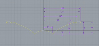
10CL51 profile


Makes me wish I had a 3D scanner, but this way is fun too")
xlim on the 10CL51 seems to be 7-8.5mm absolute max.. At that point it felt like it might rip. Good thing this is a dead driver!
10CL51 profile
Makes me wish I had a 3D scanner, but this way is fun too
xlim on the 10CL51 seems to be 7-8.5mm absolute max.. At that point it felt like it might rip. Good thing this is a dead driver!
Last edited:
Thanks for the profile JG. Pray tell how did this 10CL51 meet its demise?
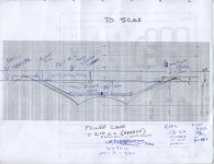
Your profile can be put into a spline in Solidworks and then a revolved surface can be made for the plug. I suppose you are doing it about the same way in 4d Cinema? I am thinking maybe soft modeling clay can be used to make an initial form to test if the HF extension is improved. If good, maybe pour plaster of paris into the cone lined with plastic and use a modeling clay form to make the negative space for the vent port opening and manifold.
Your profile can be put into a spline in Solidworks and then a revolved surface can be made for the plug. I suppose you are doing it about the same way in 4d Cinema? I am thinking maybe soft modeling clay can be used to make an initial form to test if the HF extension is improved. If good, maybe pour plaster of paris into the cone lined with plastic and use a modeling clay form to make the negative space for the vent port opening and manifold.
Don't fill the cone quite full of plaster of paris and then when the plug drops down to sit on the horn wall that "not quite full" becomes the gap you need to allow the cone to move. Could be as simple as that if the plaster of paris stands up to drilling/filing/sanding...
Thanks for the profile JG. Pray tell how did this 10CL51 meet its demise?
Your profile can be put into a spline in Solidworks and then a revolved surface can be made for the plug. I suppose you are doing it about the same way in 4d Cinema? I am thinking maybe soft modeling clay can be used to make an initial form to test if the HF extension is improved. If good, maybe pour plaster of paris into the cone lined with plastic and use a modeling clay form to make the negative space for the vent port opening and manifold.
I knew that would eventually come up, haha. Well actually the driver is not "dead", a friend decided he did not want to care about the speaker area whilst lifting the rig off of a vehicle and crunched the dust cap. This was before I knew much about repairing things myself and I deemed it "dead" when really all I needed to do was lift the dust cap from its crunched state.
For all the CAD stuff I have been using rhino, which is much more exact and operates very much like solidworks, I would imagine. It has exact boolean modeling and all the features you'd expect from a high end CAD software.
Cinema 4D I was only using to model a mockup driver before bringing it into rhino, I also used some of its modeling features to help fold my TH because of the way some of the more advanced tools can handle scale interpolation along a spline path.
For all intensive purposes here, though, it's all legit rhino CAD. I see cinema as more of a playtime art program than accurate, despite its mathematical & procedural backend.
I could whip up a revolve in rhino and make a solid out of it super easily for 3d printing, whereas it would take cinema 10x longer to calculate all the polygons.
You can easily tell what program I'm in by the color of the background, C4D is a bit darker gray and rhino is a lighter gray.
Jenny,xlim on the 10CL51 seems to be 7-8.5mm absolute max.. At that point it felt like it might rip. Good thing this is a dead driver!
Nice work on the profile! From the picture of the cardboard cutout, looks like the gasket extends only a few mm from the double roll.
On the right side of the profile, you show 42mm from the dustcap/cone juncture, could you please also include the gasket and basket rim, and if the gasket is "squishy", by how much when securely fastened?
Xlim or Xmech is the limit when things rip, or the voice coil gets smashed.
I had four Eminence Kappa 10" ( 3.2mm Xmax, 10.9mm Xlim) that actually tore the cones all the way around at various places near the surround when a Crest CA9 amp dumped the full voltage of the DC portion of the power supply to the case (a retaining nut had loosened up). Probably a capacitive discharge of 120 volts or more.
Sounded like a shotgun blast, but amazingly, the voice coils were all unharmed. I patched the speakers up, and they all worked fine, other than the FS was lowered by the extra weight of the patch material.
If the 10CL51 surround were to be straightened out (as in driving to Xlim), it's length would increase to about 22mm, which would appear to allow almost a 20mm distance above the 38mm/98mm intersection point. An 8.5mm Xlim seems very little for a speaker with 6mm Xmax, generally most modern PA woofers are built for Xlim being around double (or more) Xmax.
When you measured 8.5mm forward, did you pull the surround or spider flat?
Thanks,
Art
You caught me just in time! I was about to go to bed. I know you were hoping to get started today though so I went ahead and added the details- hopefully I got 'em all!
As far as xlim, I might be getting 10mm out of it using both hands. The surround does not seem to want to stretch flat, almost like it's got tons of glue that keeps it holding its shape. The surround is like a hardened cloth, not that flexible.
On a scale of 0 soft as heck to 10 hard as a rock I would rate the gasket about a 7 or 8, it really doesn't want to squish much at all- definitely no mushroom action on it. I think the metal casing would bend to heck before that foam came down more than a fraction of a mm.
Here are the new measurements. I made some good adjustments to the surround and added the gasket and metal casing. It's another mm more accurate and I triple checked for consistency
I bet that surround works more like a hinge point rather than a linear motion like a half roll rubber surround - which would definitely need more clearance. I am thinking 2 mm of motion at the stiff surround is sufficient to get 12mm motion at dust cap. Easy to check with a straightedge across the top and use hands to push surround and cone forward until cloth surround touches. Probably can't be done very easily by hand as that is a whole lot of magnetic force circa 50 volts plus on a 12 Bl motor. I gotta imagine that he spider and surround are stiffer than heck to withstand that kind of motor force.
To be safe it wouldn't hurt to put a 5mm deep spacer or router a channel into the mounting board for safer clearance.
Thanks for doing this JG. Very accurate results are nice. Why don't manufacturers provide this info on their data sheets?
Get some sleep.
To be safe it wouldn't hurt to put a 5mm deep spacer or router a channel into the mounting board for safer clearance.
Thanks for doing this JG. Very accurate results are nice. Why don't manufacturers provide this info on their data sheets?
Get some sleep.
Been reading thus far and interested in this build for PA is it possible to use 10PR300 I have 2 laying around needs new Synergy home? Thanks! Sorry to Hijack this tread
With two 10PR300's put into JG's short horn described previously in my hand sketch you can get a 124dB at 2.83v speaker with 49 volts to hit xmax.
Attachments
Hi xrk971 Great I can get more 10 PR's and Faital 1.4 is nice also the Celestion 1.4 previuosly mentioned is kinda expensive, I also have a sheet of 12 mm Baltic Birch ready to be cut up if plans are out? I've always wanted to do a horn like this raised above the crowd, thanks for the reply keep it coming!
Most cabinets for this speaker simply front or rear mount, so cone profile dimensions aren't needed. For this application, the information Jennygirl provided is vital.To be safe it wouldn't hurt to put a 5mm deep spacer or router a channel into the mounting board for safer clearance.
Thanks for doing this JG. Very accurate results are nice. Why don't manufacturers provide this info on their data sheets?
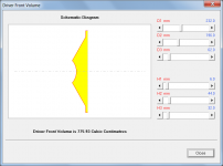
I plan to rout a 6mm x 36mm channel to prevent the cone or surround from hitting the baffle, unfortunately that adds about 131cc to the 847 cc cone volume (thanks again for that info Jenny).
I will mill cone fillers from plywood with the baffle side dimension 155mm, cone side 78mm, 19mm deep, approximately 210cc. So it looks like the VTC (per cone, x2 for Hornresp) will be in the range of 768cc- not good, sports fans
. Conforming to the dust cap contours exactly would make little difference in the volume reduction.
The relief channel has to be routed before the horn is assembled, and I will be testing the HF horn before the 10" BP ports are cut, so position and size of the port holes influence on frequency and polar response can be tested. Fortunately, the cone filler will allow multiple shapes and sizes to be tested without having to junk the horn.
Sawdust time for the wood butcher!
Art
Attachments
Guys,
On yout Hornresponse models, shouldn't you be configuring AP1 rather than AP for an offset horn?
Neat project though. Since I'm designing for a home system I'm going a different direction-- to a half-inch HF driver for better pattern control at very high frequencies, and a box that doesn't pattern flip. I'll be watching this thread though to see how it comes out.
Guys,
On yout Hornresponse models, shouldn't you be configuring AP1 rather than AP for an offset horn?
Neat project though. Since I'm designing for a home system I'm going a different direction-- to a half-inch HF driver for better pattern control at very high frequencies, and a box that doesn't pattern flip. I'll be watching this thread though to see how it comes out.
Bwaslo,
If doing a home system consider using a 3in full range driver like the Faital Pro 3FE22 with a 2in square throat for a tractrix. I found that it can sound quite nice and have super high sensitivity.
Look here for more info: http://www.diyaudio.com/forums/full-range/261427-presenting-trynergy-full-range-tractrix-synergy.html
Bill,Guys,
On yout Hornresponse models, shouldn't you be configuring AP1 rather than AP for an offset horn?
I have not updated to the most recent Hornresp, the version I'm using just has AP (Port Area)/LPT(length of port) for the bass reflex portion, and a VTC (Volume of Throat Chamber)/ATC(Area of Throat Chamber) selections for the offset horn port, and the length of the VTC is a fixed value of 19mm, IIRC.
Your calculator is fabulous! I was just about to write you that there was a "glitch", when I discovered the reason it was not agreeing with my "scale drawings" in the first post was I had drawn them two different lengths, and also had made an angle error (doh..).
Considering the bass reflex two-way SyntripP will have roughly 1536 cc ATC (between the two 768cc BC H10CL drivers using a cone area filler), what ATC (and length) would you choose?
Art
Last edited:
Hi Art,
You can cycle through parameter types (by clicking the name in that spot -like "AP")? Or by using some key (F6?) ? I forget, and I'm not near a pc at the moment to check. But it's there at least as of several years ago. Hard to find in the HR docs, though. It does make a difference.
Glad you like the spreadsheet - there's a later version of that which also shows the vertical directivity cutoff angle (though it's not hard to calculate it). Not sure if I ever posted the revised spreadsheet though (life's been kind of hard to keep up with this past year! ).
unfortunately that adds about 131cc to the 847 cc cone volume
Hi Art,
Based on the dimensions given in Attachment 1, Hornresp calculates the cone volume to be 776 cc. Because the surface of the cone is curved, the true volume will be slightly less. The actual volume is therefore somewhat smaller than the 847 cc figure you are assuming.
Kind regards,
David
Attachments
Hard to find in the HR docs, though.
Search for references to Ap1 using the File > Find tool in the Hornresp Help file.
Except that Jennygirl measured the volume with water - maybe that includes height of foam gasket?
In any event, I think that the tool in HR can be used to design a conformal plug with say 10mm of clearance to estimate the volume reduction ( sans flow duct cutout). I think 450ml net volume should be doable as 510cm2 x 1cm=510cm3. 850-510=340cm3. That leaves 110cm3 for the duct cutout. I think Weltersys' generous cutout donut to allow surround clearance is too generous - make it a shallow 5mm deep and only wide enough where the max extent of the cloth accordion would actually touch in max excursion.
In any event, I think that the tool in HR can be used to design a conformal plug with say 10mm of clearance to estimate the volume reduction ( sans flow duct cutout). I think 450ml net volume should be doable as 510cm2 x 1cm=510cm3. 850-510=340cm3. That leaves 110cm3 for the duct cutout. I think Weltersys' generous cutout donut to allow surround clearance is too generous - make it a shallow 5mm deep and only wide enough where the max extent of the cloth accordion would actually touch in max excursion.
Last edited:
- Status
- This old topic is closed. If you want to reopen this topic, contact a moderator using the "Report Post" button.
- Home
- Loudspeakers
- Multi-Way
- Synergy Tripp 10"