Greets!
Right, we're dealing with eigenmodes [standing waves], which can develop wherever there's an acoustical impedance mismatch, be it a cone driver, horn mouth, baffle edge, etc. and a circle constitutes a continuous parallel surface, so will sum to a much higher intensity than a single eigenmode of the same distance.
So, we have the one going across the driver's gasket, one from the port terminus, ones from it and the driver's gasket and of course any obstruction such as a phase plug and/or an insert to reduce the chamber's volume will affect these and why you see them 'moving around' in frequency.
In short, no practical way to get rid of them, only reduce their intensity either by damping them and/or by making them random in shape, same as we do with any confined space.
No clue what all software/simming capability Tom has, but a good starting point would be one of the programs that sims automotive/whatever piston/cylinder head 'squish' chambers if there's nothing available specifically for acoustic apps.
GM
Right, we're dealing with eigenmodes [standing waves], which can develop wherever there's an acoustical impedance mismatch, be it a cone driver, horn mouth, baffle edge, etc. and a circle constitutes a continuous parallel surface, so will sum to a much higher intensity than a single eigenmode of the same distance.
So, we have the one
In short, no practical way to get rid of them, only reduce their intensity either by damping them and/or by making them random in shape, same as we do with any confined space.
No clue what all software/simming capability Tom has, but a good starting point would be one of the programs that sims automotive/whatever piston/cylinder head 'squish' chambers if there's nothing available specifically for acoustic apps.
GM
yes, it is obvious and equally obvious that its not my problem. My vent is only 1.5 inches long...so I'm still in a quandary.
what I'm seeing looks more like a cancellation null... but the frequency is a little bit too low to be related to the driver cone width. OTOH different versions of phase/volume plugs have moved it around.
I'm going to swap in some 6" mids tomorrow and see if the finger gets pointed at the horn or stays on the driver.
Post your measurment so we can see what these cancellation nulls look like. Are you running the 8FE200's open back right now? If so there will be a cancellation null equal to diatance from the injection port to the horn mouth and then back to the driver back - about 150Hz in a typical synergy. Once you close the back with a box that will go away.
measurements
Thanks for asking")
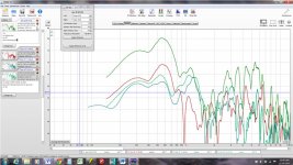
Here is a collage of REW measurements comparing results with and without phase/volume plug. I've been a little disorganized and I'm trying to fix that but this is the best I have at this time. These are all taken at different times and volumes so absolute SPL is meaningless.
Green (at top) is with no phase plug and no CD. Only problem is the lack of bandwidth. I don't understand why it falls off so soon but that clearly isn't an eigenmode problem.
Red (next one down) is with a truncated cone volume plug with the holes through the horn wall simply continued through the volume plug. The edge of the hole is at the edge of the base of the volume plug. The volume plug added the sharp null and made very little other difference. The null, I’m guessing, is a standing wave phenomenon.
The volume plug is a ¾” thick truncated cone; 5.5” dia on the bottom, 3.5” dia on the top; the bottom of the dust cap comes within 1/8" to 3/16" of it. I don't want/need more than 3mm of travel...
In the next measurements I took the CD off the back so as not to be confused by its reflection null. With the CD off, the apex's reflection null is high enough in frequency to not confuse the picture around 1 Khz.
Green, the next one down, is where I closed off the original holes in the volume plug, hollowed it out somewhat to create a duct to a new hole in the top of the truncated cone. This hole was 1 3/8” diameter (my largest forstner bit) and offset from center towards my horn wall holes to minimize duct length. I tried filling the excess volume in the “duct” with putty to make it more like a duct and less like a chamber and saw some low pass filtering as a result. That is probably worth another picture. In retrospect, HR says I should have made a larger hole.
Blue is another variant of the phase plug. I shaped grooves across the top towards the far side of the cone to try and minimize the distance that sound had to travel from that side. This is, I think a dead end.
I think its significant that in these last two configurations I still have the early SPL drop off but the phase/volume plug allows the SPL to come back up once the frequency gets past the null. That is probably just showing the lack of acoustic filtering. The plug has a volume of 195 cc. Cone traps 425 cc.
Well I just routed another phase plug blank but I think I'll wait for your thoughts before I do more than shape it to the cone.
Jack
Thanks for asking
Here is a collage of REW measurements comparing results with and without phase/volume plug. I've been a little disorganized and I'm trying to fix that but this is the best I have at this time. These are all taken at different times and volumes so absolute SPL is meaningless.
Green (at top) is with no phase plug and no CD. Only problem is the lack of bandwidth. I don't understand why it falls off so soon but that clearly isn't an eigenmode problem.
Red (next one down) is with a truncated cone volume plug with the holes through the horn wall simply continued through the volume plug. The edge of the hole is at the edge of the base of the volume plug. The volume plug added the sharp null and made very little other difference. The null, I’m guessing, is a standing wave phenomenon.
The volume plug is a ¾” thick truncated cone; 5.5” dia on the bottom, 3.5” dia on the top; the bottom of the dust cap comes within 1/8" to 3/16" of it. I don't want/need more than 3mm of travel...
In the next measurements I took the CD off the back so as not to be confused by its reflection null. With the CD off, the apex's reflection null is high enough in frequency to not confuse the picture around 1 Khz.
Green, the next one down, is where I closed off the original holes in the volume plug, hollowed it out somewhat to create a duct to a new hole in the top of the truncated cone. This hole was 1 3/8” diameter (my largest forstner bit) and offset from center towards my horn wall holes to minimize duct length. I tried filling the excess volume in the “duct” with putty to make it more like a duct and less like a chamber and saw some low pass filtering as a result. That is probably worth another picture. In retrospect, HR says I should have made a larger hole.
Blue is another variant of the phase plug. I shaped grooves across the top towards the far side of the cone to try and minimize the distance that sound had to travel from that side. This is, I think a dead end.
I think its significant that in these last two configurations I still have the early SPL drop off but the phase/volume plug allows the SPL to come back up once the frequency gets past the null. That is probably just showing the lack of acoustic filtering. The plug has a volume of 195 cc. Cone traps 425 cc.
Well I just routed another phase plug blank but I think I'll wait for your thoughts before I do more than shape it to the cone.
Jack
Attachments
Greets!
Right, we're dealing with eigenmodes [standing waves], which can develop wherever there's an acoustical impedance mismatch, be it a cone driver, horn mouth, baffle edge, etc. and a circle constitutes a continuous parallel surface, so will sum to a much higher intensity than a single eigenmode of the same distance.
So, we have the onegoing across the driver's gasket, onefrom the port terminus, ones from it and the driver's gasket and of course any obstruction such as a phase plug and/or an insert to reduce the chamber's volume will affect these and why you see them 'moving around' in frequency.
In short, no practical way to get rid of them, only reduce their intensity either by damping them and/or by making them random in shape, same as we do with any confined space.
No clue what all software/simming capability Tom has, but a good starting point would be one of the programs that sims automotive/whatever piston/cylinder head 'squish' chambers if there's nothing available specifically for acoustic apps.
GM
Hi Greg
“No clue what all software/simming capability Tom has, but a good starting point would be one of the programs that sims automotive/whatever piston/cylinder head 'squish' chambers if there's nothing available specifically for acoustic apps.”
Well, the big difference between what goes on here and in other threads vs what I do is that I use models to help understand how things work BUT the driving element is the measured result for what I am modeling and not the predicted result.
The problem with models from Pspice to Akabak and so on is that they are exquisitely accurate which also means you get an accurate answer BUT it is limited to what you have included in your model.
For instance, in an electrical model the simple case would have an inductor as just an inductor but to predict what one sometimes measures in circuit, the inductor has to also have a series R and for higher frequencies, you need to add several more parts to the model to predict what you measure from the real thing.
When one draws a horn and composes a model, one is also in that zone where the model is as complete as your idea about what you’re modeling, how many secondary things you have added . Make a bass horn, measure it and then make a model based on the physical item and what do you see?
Do you see exactly what you measure? Usually No you don’t, there are secondary elements you have not included and so general features in the low frequency side may be predicted but other things predicted do not exist in the measurement.
For example, how does one model the degree the horns walls or radiator cone flex or tiny air leaks or viscous losses? You CAN model all of these things and get a model prediction that is very close to the measured result, but only after tweaking the model of what you built and adding a few secondary things.
For instance, in #196, the very sharp peaks and nulls in the above 500Hz range would generally either be much lower “Q” features or mostly non-existent.
There are a series of cancellation notches which begin at a frequency where the reflected sound from the acoustic closed end returns 180 degrees behind and then at every odd half wavelength spacing above that.
Bottom line, a proper measurement of the real thing trumps any computer model of same.
Best,
Tom
Hi Tom:
I came here seeking an explanation for something I saw in a measurement and didn't understand. If I can take that understanding (assuming I arrive at it) and then augment my simulation model to reproduce the previously unknown phenomenon, (or if I can just make the proto work) then I can move ahead with confidence.
My attitude towards simulation is substantially the same as yours, but with a difference. In my day job I feed architectures and algorithms into a team of ASIC design engineers. They sometimes simulate for upwards of a year before they say done. The reason for that is it costs almost $2 million and 6 months to get a prototype of a chip in the latest technology from the time you declare you've simulated enough. It could take another year to fix a bug. Still, when we get a new chip out in the lab we figure that in a few seconds we run many more cycles through that chip than we ever did with a team of engineers and 100 computers simulating 24x7 for a year.
Audio is such a nice change from that high pressure paradigm!
Jack
Hi Jack
It looks like you posted 203 while I was writing.
If you’re dealing with “small and fast” / high Di/Dt, then your modeling software is much more involved than what one deals with in acoustics.
What I see in your measurements would be the response of a larger driver. The upper limit to horn loading is set (among other things) by the size of the radiator relative to the wavelength.
If you wanted to get up to say 1Khz or a little higher, you would need about a 5 inch driver as hinted at in the radiation resistance curve vs radiator size with an appropriate internal horn dimension and port locations..
Hope that helps
Tom
Hi Tom:
We use Spice for the analog and I/O but most engineers are just dealing with ones and zeros....
My design uses two 8" midsand was to be a 2-way. I'm beginning to see why one can't use a radiator much more than half a wavelength in diameter at the Xover. I was hoping to beat that with a phase plug. Art Weltersys just did a 2-way with 10" drivers, as documented in this thread, which encouraged me to try. I was going to flatten out that horn gain peaking in the last octave to make it work. Its just the nosedives just under 1 Khz that are killing me or rather costing me headroom. But I have made DSP crossovers with these measurements using a PEQ term to prop up the mid response under the null.
Jack
nc535, you noted that different "phase plugs" (forgive me for only skimming the thread as I wait to clock in), behind the injection port (between driver face and horn wall if I'm not mistaken) "shifted" the nulls you saw in measurment.
Have you experimented with different injection port *shapes* (maintain similar CSA) as well as the rounding/chamfering methods seen on many diy synergy builds? If so... what effects on the nulls/overall frequency response did it have?
Have you experimented with different injection port *shapes* (maintain similar CSA) as well as the rounding/chamfering methods seen on many diy synergy builds? If so... what effects on the nulls/overall frequency response did it have?
Nope, I haven't gotten that far yet and hope I don't have to. I'm crossing to subs high enough that mid port particle velocity won't be especially high and so I won't need those optimizations. If you want to see what shapes work though, all you have to do is browse Danley's web site!
Synergy midrange measurement.
Hello to all.
Being a fan of Synergy conception I was following for it for 16 (?) years from Tom Danley Unity.
So I have build Bwaslo synergy, I also got PSE144 and my last experiments was Art Weltersys Tripp 10.
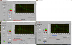
First of all I would like to say big thanks to all of you guys. With out of your support this thing will be impossible. So bellow it's a measurement of all of them. I tried PSE144 with and without xover with 2 and 4 mids. Tripp 10 I tried with 5-6 different drivers. The most interesting are B&C, JBL2123H and Isophon P170. For 6.5" Isophon I use only one port on each side and lot's of experiments with cone correction. I want to mids go up to 900hz. Finally on JBL with third variant of cone correction and 5-th for Isophon I got this:
Old Synergy - Bwaslo version.
Synergy -PSE144
The first graphic should be last.
.JPG")

Hello to all.
Being a fan of Synergy conception I was following for it for 16 (?) years from Tom Danley Unity.
So I have build Bwaslo synergy, I also got PSE144 and my last experiments was Art Weltersys Tripp 10.
First of all I would like to say big thanks to all of you guys. With out of your support this thing will be impossible. So bellow it's a measurement of all of them. I tried PSE144 with and without xover with 2 and 4 mids. Tripp 10 I tried with 5-6 different drivers. The most interesting are B&C, JBL2123H and Isophon P170. For 6.5" Isophon I use only one port on each side and lot's of experiments with cone correction. I want to mids go up to 900hz. Finally on JBL with third variant of cone correction and 5-th for Isophon I got this:
Old Synergy - Bwaslo version.
Synergy -PSE144
The first graphic should be last.
Attachments
Last edited:
- Status
- This old topic is closed. If you want to reopen this topic, contact a moderator using the "Report Post" button.
- Home
- Loudspeakers
- Multi-Way
- Synergy Tripp 10"