Did the 12k dip show up in sims or is it purely a driver issue?
It is specific to the driver - although if I had a detailed internal geometry specific model of the Celestion driver in Akabak, it may capture that resonance dip which corresponds to a 0.71 inch (half-wave) internal reflection distance somewhere between the diaphragm and solid surface somewhere internally.
Paul,Did the 12k dip show up in sims or is it purely a driver issue?
I did not sim the HF response of a 1.4" driver. It is a driver issue, as explained in #177, different phase plug/diaphragm designs all have their own issues.The glitches in that region show up in Celestion's measurements, but they use enough smoothing that it does not look as bad as what my measurements display.
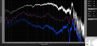
The graph below compares the CDX14-3050 driver on a Welter Systems Maltese conical expansion horn (13 x 13 degree horn angle) in the middle trace, and it on the Welter Systems SynTripP in the lower trace. It is clear that the peaks and dips are at the same exact frequencies, while an EV DH1AMT-16, a 3" diaphragm "pancake" driver using a different phase plug approach shows peaks and dips at different frequencies on the same Maltese horn.
Note how the purple trace looks much smoother than the others- it was measured using FPPO (fixed point per octave), which only has a resolution of 1/24th octave, reducing the dips and peaks by about 50%, while the others measured used FFT at 32K for a resolution of just 1.5 Hz "tell it like it is".
That said, our hearing resolution is not much better than 1/6th octave, so some would argue 1/24th octave is more than enough.
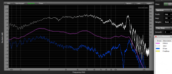
In the "Smooth" screen shot, smoothing of "9" is applied, now the response looks almost perfect (for a constant directivity horn) with a gradual 5 dB drop from 1600 Hz to 14 kHz, then a drop to -10dB at 17kHz.
Art
Attachments
X,Are these typical harmonic distortion levels for this driver? It seems a bit high to me and I wonder if it is higher than usual, perhaps cabinet wall vibrations may be contributing.
Cabinet wall flex using 1/2" plywood for a HF horn the size of the SynTripP is a non-issue.
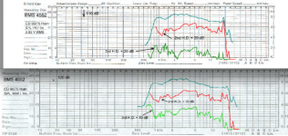
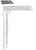
Comparing distortion tests on different horns takes some interpretation. If we compare distortion at 1600 Hz, we see that the EV NDYM 1-16 on an EV HP9040 horn has the second harmonic down about 22 dB from the 110 dB fundamental, 7.9% distortion, compared to the SynTripP with the Celestion CDX14-3050-16 having a 110.4 dB fundamental with second harmonic down -39.2dB, only 1.1% . Raising the drive level to 5 watts hardly increases the distortion with a good 3" diaphragm driver.
The EVHP9040 is a similar size to the SynTripP, but uses a pinched throat to achieve it's wide dispersion, it's throat design coupled with the NDYM' driver's long throat neck design allows it to load well, and have flat response to around 450 Hz, while the conical SynTripP/CDX14-3050 is around -12 dB at 450 Hz. At 600 Hz, the SynTripP is about -6dB compared to the EVHP9040, so it's distortion is higher.
The 1" exit BMS 4552 uses an annular diaphragm with slightly more Sd (diaphragm area) than the B&C DE250 you have been using as a model, but much less Sd than 3" diaphragm drivers. The distortion specs of the 4552 on a 9075 horn show it to have a bit less distortion at 1600 Hz 1 watt than the EV, but more than the CDX14-3050.
When power is raised by 10 dB (10 watts), distortion rises by 10dB, and the 4552 now has near 18% distortion at 1600 Hz, and at 600 Hz, would be somewhere in the 100%(!) range at only about 106 dB, compared to the SynTripP/CDX14-3050 at 2 watts producing 107.1 dB with 5.6% distortion.
I have not put the SynTripP through extensive distortion testing, but the CDX14-3050 seems to have quite low distortion in the pass band it will likely be used.
This thread has a lot of compression driver info, and allows you to listen to recordings of different drivers at different drive levels, all equalized flat:
http://www.diyaudio.com/forums/multi-way/212240-high-frequency-compression-driver-evaluation.html
Enough with the HF, I'm on my way to the shop to make some plugs and cut some holes for the 10" drivers!
Art
Attachments
Last edited:
The Effect of Bass Injection Port Dia
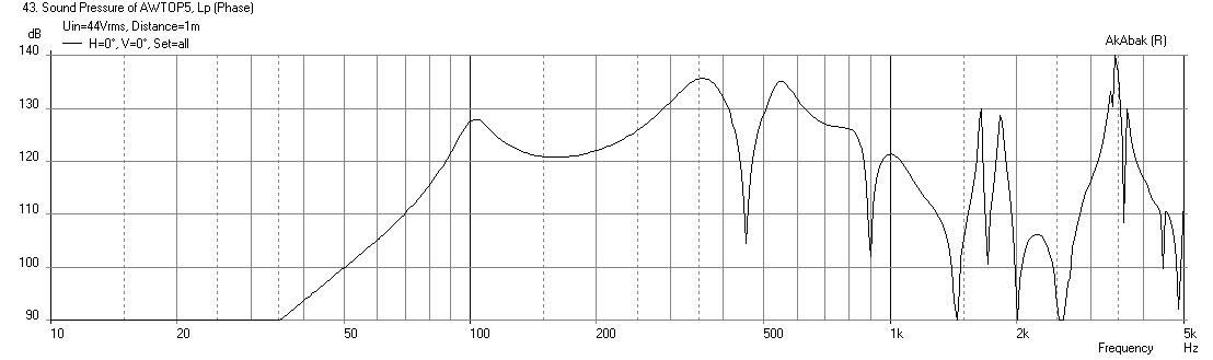
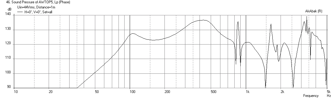
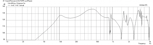
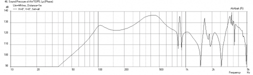
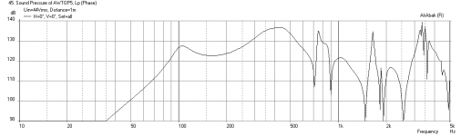
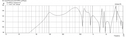
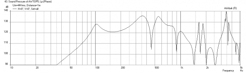
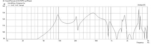
If the bass injection ports are relocated to 50mm from the apex (measured axially) and assuming a 20mm average port depth due to the volume plug in the driver chamber, we get the following predicted responses for injection port diameters ranging from 0.75in dia equivalent CSA to 4in dia. It looks like above 3.5in dia is the point of diminishing returns on getting reducing the saddle in the response. This is assuming a 30 liter rear chamber and qnty 4 x 3.0in dia x 7.5in long bass reflex ports connected at 12in axial location from the apex. The driver chamber front volume is assumed to be 768 cc.
0.75in dia injection port:

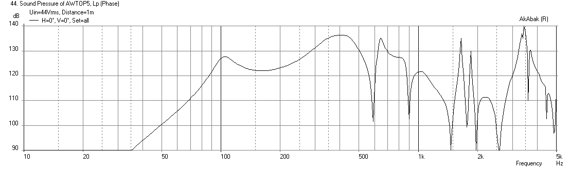
1.50in dia injection port:
2.00in dia injection port:
2.50in dia injection port:
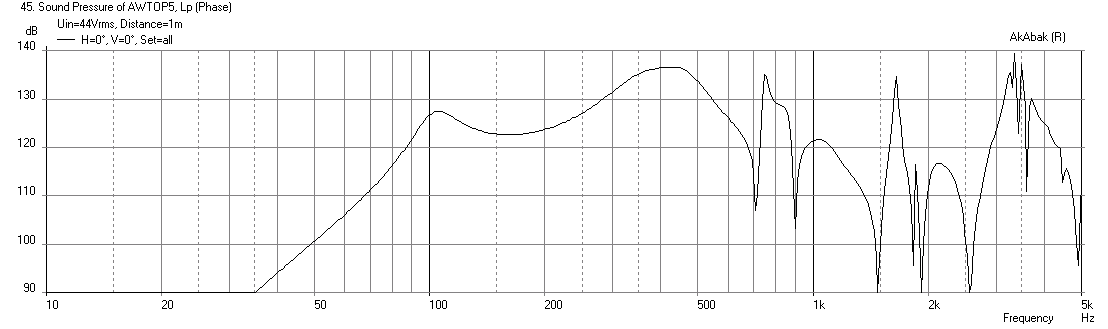
3.00in dia injection port:
3.50in dia injection port:

4.00in dia injection port:
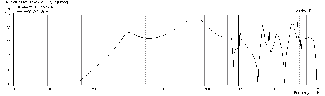
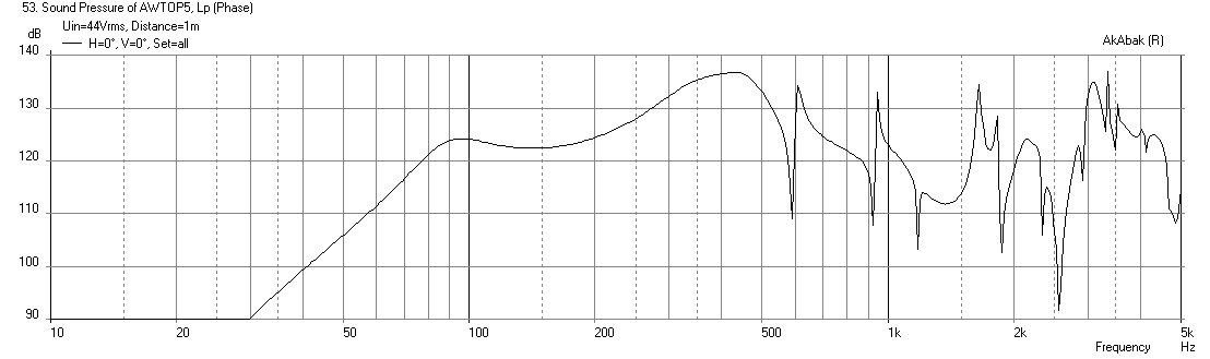
If you use a longer BR vent of 11.5in to get reduce the saddle shape, you get a port resonance cancellation dip at about 600Hz and this could be a problem for the XO region (3.5in dia injection port):
If the bass injection ports are relocated to 50mm from the apex (measured axially) and assuming a 20mm average port depth due to the volume plug in the driver chamber, we get the following predicted responses for injection port diameters ranging from 0.75in dia equivalent CSA to 4in dia. It looks like above 3.5in dia is the point of diminishing returns on getting reducing the saddle in the response. This is assuming a 30 liter rear chamber and qnty 4 x 3.0in dia x 7.5in long bass reflex ports connected at 12in axial location from the apex. The driver chamber front volume is assumed to be 768 cc.
0.75in dia injection port:
1.50in dia injection port:
2.00in dia injection port:
2.50in dia injection port:
3.00in dia injection port:
3.50in dia injection port:
4.00in dia injection port:
If you use a longer BR vent of 11.5in to get reduce the saddle shape, you get a port resonance cancellation dip at about 600Hz and this could be a problem for the XO region (3.5in dia injection port):
Attachments
-
 Awtop6-inj-port-4.00in-dia-at-50mm.png14 KB · Views: 1,698
 -
 Awtop6-inj-port-3.50in-dia-at-50mm.png13.9 KB · Views: 1,698
 -
 Awtop6-inj-port-3.00in-dia-at-50mm.png14.1 KB · Views: 1,751
 -
 Awtop6-inj-port-2.50in-dia-at-50mm.png14.1 KB · Views: 1,760
 -
 Awtop6-inj-port-2.00in-dia-at-50mm.png14.1 KB · Views: 1,763
 -
 Awtop6-inj-port-1.50in-dia-at-50mm.png25.6 KB · Views: 1,764
 -
 Awtop6-inj-port-0.75in-dia-at-50mm.png25.6 KB · Views: 1,776
 -
 Awtop6-inj-port-3.50in-dia-at-50mm-11.5in-vent.png16.2 KB · Views: 1,698
Last edited:
X,If the bass injection ports are relocated to 50mm from the apex (measured axially) and assuming a 20mm average port depth due to the volume plug in the driver chamber, we get the following predicted responses for injection port diameters ranging from 0.75in dia equivalent CSA to 4in dia. It looks like above 3.5in dia is the point of diminishing returns on getting reducing the saddle in the response. This is assuming a 30 liter rear chamber and qnty 4 x 3.0in dia x 7.5in long bass reflex ports connected at 12in axial location from the apex. The driver chamber front volume is assumed to be 768 cc.
Thanks for the additional sims!
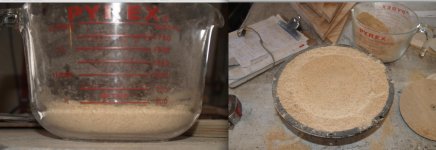
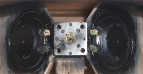
Unfortunately, I had forgotten to give you the results of my cone fill test with the filler cone, looks like the throat chamber volume (ATC) per driver is around 500 cc, around 1000 ATC.
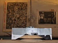
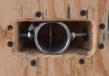
Installing the pole tilt assembly after the horn was already installed in the cabinet was like building a ship in a bottle, it took probably five times the time it would have if done in the proper assembly procedure.
The initial port test will use ports around 3.125 square inch (21 square centimeters) total. Still have to wire up the input connectors, cut bass reflex ports, staple on some fiberglass fill, and install the drivers before the first test of round two...
Art
Attachments
Last edited:
If volume is 500cc vs 768cc you should have extended response up in the HF bandpass. This is good as if will give you more latitude on the XO point. The volume plugs and ports look great. I see your pole mount looks like a lot of work - I wonder if an external 4bolt screw on boss might have been easier? This is certainly clean though. Is there a way you can measure the main rear chamber volume using something like foam peanuts? I guess the calcs should be enough to get into the right ball park. Great progress though and I can see that is a substantial project and investment of time. Will be worth I though to have such a compact point source with 125dB capability. 
I have managed to dispose of all foam peanuts, so don't have a suitable alternative other than water to test volume (not going to happen), but I think my estimate is "close enough for rock and roll". At any rate, I will be tuning the ports to make a 70 Hz Fb by whatever means needed.I see your pole mount looks like a lot of work - I wonder if an external 4bolt screw on boss might have been easier?
Assembling a separate bracket for each gig is time consuming, but worse, it would lower the tilt point by 3" or so, moving the weight forward or backwards much more than my internal arrangement.
Nimrod Webber invented an external "Balanced Tilter" that elegantly overcomes the weight transfer problem entirely, but it is quite expensive and a bit bulky.
Preliminary tests of the SynTripP tilter indicate that even with the second portion of the horn attached, at maximum down tilt there should only be about a 10 pound forward offset. Since the mouth will be around 7 square feet, I will be using guy lines to the sub cabinet (which serves as the pole base) to keep it from spinning in the wind, they will eliminate any forward stress the shift in CG causes.
Without the second portion, the CG is behind the pole when straight forward, at the maximum 20 degree down tilt CG moves slightly forward of the pole.
Back to the sawdust factory...
Art
Last edited:
Normally, I take my mental time estimate for a project and double it, and it's about right. About 200 hours later, I think I was short in that estimation by about 6 dB, but it appears the SynTripP is also exceeding the simulations by a few dB also.How's this project going, Art?
Just about to finish the second horn section strap/bridal section, then test polars again.
Hopefully the wind will remain calm, the last test session with the second section horn prototype ended abruptly
Attachments
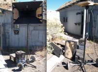
Not fair wish you future better luck......the last test session with the second section horn prototype ended abruptly
Like Timbuk 3 sang, "The Future's so Bright I gotta wear Shades".Not fair wish you future better luck.
Here are the results :
http://www.diyaudio.com/forums/mult...ual-single-point-source-horn.html#post4114406
Even though I've devoted full time for the last month in the development, I'm really pleased with the results.
Art
Last edited:
On the other hand, having CNC is a major bonus for future builds.
I have a CNC router that I'd be happy to donate time on to the cause.
I have a CNC router that I'd be happy to donate time on to the cause.
Thank you for the offer! I will keep that in mind for folks I work with in the LA area. I think the above quote was from a message to Jennygirl who was moving to a new warehouse location with a shared CNC machine. She is in LA too. Wish you were in NoVA.
Cheers,
X
Why these nulls?
Did you spend any time thinking about what causes the nulls just below 1 Khz in these simulations?
I built a similar horn over the holidays (90x45 using 8FE200s for bass) and I too am seeing a null in that region- between 750 and 950 hz depending on what I've done to try to get rid of it and how I'm looking at it. I know, in my case at least, its not the 1/4 lambda reflection from the CD diaphragm because I get the same/similar null with the CD removed and its hole either left open or plugged or with either a DNA 360 or a BMS4550 hanging on to it.
I was speculating that the null is due to the mid port holes being at the edge of the surround while the most distant part of the cone is almost 7.5" away, more with a volume plug in place. I doubt this effect is covered in your Akabak simulation yet the simulation shows a null so perhaps there is another explanation. Any ideas?
Thanks in advance,
Jack
Port resonance cancellation DIP is a possibility I hadn't thought about till now. I've been testing either open back or really leaky foam board sealed back with a bass reflex vent in the design. Funny how just telling someone about a problem can open your mind to a possibility
If the bass injection ports are relocated to 50mm from the apex (measured axially) and assuming a 20mm average port depth due to the volume plug in the driver chamber, we get the following predicted responses for injection port diameters ranging from 0.75in dia equivalent CSA to 4in dia. It looks like above 3.5in dia is the point of diminishing returns on getting reducing the saddle in the response. This is assuming a 30 liter rear chamber and qnty 4 x 3.0in dia x 7.5in long bass reflex ports connected at 12in axial location from the apex. The driver chamber front volume is assumed to be 768 cc.
0.75in dia injection port:
1.50in dia injection port:
2.00in dia injection port:
2.50in dia injection port:
3.00in dia injection port:
3.50in dia injection port:
4.00in dia injection port:
If you use a longer BR vent of 11.5in to get reduce the saddle shape, you get a port resonance cancellation dip at about 600Hz and this could be a problem for the XO region (3.5in dia injection port):
Did you spend any time thinking about what causes the nulls just below 1 Khz in these simulations?
I built a similar horn over the holidays (90x45 using 8FE200s for bass) and I too am seeing a null in that region- between 750 and 950 hz depending on what I've done to try to get rid of it and how I'm looking at it. I know, in my case at least, its not the 1/4 lambda reflection from the CD diaphragm because I get the same/similar null with the CD removed and its hole either left open or plugged or with either a DNA 360 or a BMS4550 hanging on to it.
I was speculating that the null is due to the mid port holes being at the edge of the surround while the most distant part of the cone is almost 7.5" away, more with a volume plug in place. I doubt this effect is covered in your Akabak simulation yet the simulation shows a null so perhaps there is another explanation. Any ideas?
Thanks in advance,
Jack
Port resonance cancellation DIP is a possibility I hadn't thought about till now. I've been testing either open back or really leaky foam board sealed back with a bass reflex vent in the design. Funny how just telling someone about a problem can open your mind to a possibility
Last edited:
I did think about it and it is indeed port resonance cancellation. This was obvious when you look at the velocity in the ports - the max velocity peak corresponds to the nulls. This is why it is preferable to keep port length shorter so that resonance is above pass band of 1kHz. Or a port should be no longer than 6.75 in long (half wave length of 1kHz). If you have bass reflex injection holes they need to be shorter than 6.75in and if that is too short to get bass extension you need then you need more skinny and shorter ports rather than fewer big and longer ports.
Last edited:
yes, it is obvious and equally obvious that its not my problem. My vent is only 1.5 inches long...so I'm still in a quandary.
what I'm seeing looks more like a cancellation null... but the frequency is a little bit too low to be related to the driver cone width. OTOH different versions of phase/volume plugs have moved it around.
I'm going to swap in some 6" mids tomorrow and see if the finger gets pointed at the horn or stays on the driver.
Hi GM:
Thanks GM but I'm not sure what you are saying. Could you explain a little for someone who has some (rusty) mathematical background but tends to use it only as a last resort
I've been theorizing this is a cancellation phenomena. The port holes through the horn wall are close to the edge of the mid cone. At the holes, waves from nearby points on the cone are summed with waves from the far edge and this could well lead to partial cancellation where the path length difference is half a wavelength. I've seen the null frequency shift with the introduction of a volume plug but I've not yet succeeded in designing one that makes the null disappear.
Thanks,
Jack
- Status
- This old topic is closed. If you want to reopen this topic, contact a moderator using the "Report Post" button.
- Home
- Loudspeakers
- Multi-Way
- Synergy Tripp 10"