Cookiemonster,
The Hughes Quadratic throat is "sound", but in terms of usefulness for a horn using a HF driver and offset mid drivers, not very, as it's shape requires moving the mid driver entrance further from the HF driver entrance, which then requires delay correction to bring the drivers into alignment.
Art
Weltersys,
Your current design has the mid port at 5.25in from the throat IIRC, is that really a problem to have and the Hughes quadratic throat? To me, it seems like a 3d adapter that performs the Hughes expansion and has a mounting boss for the mid driver can also work. If one has the luxury of 3d printing, it seems to be a solvable engineering exercise. Making it out of plywood may be next to impossible though. (has anyone done a 3d printed Paraline? seems a perfect application for 3d printing...)
(has anyone done a 3d printed Paraline? seems a perfect application for 3d printing...)
To me it seems more affordable to use water jet or laser cutting in aluminium for a stacked construction like a Paraline. Easy to do with 2D cad drawings and a bit of work (if you want 45 degree corners etc.)
What material would you choose for 3D printing something like a Paraline?
3d printing can be relatively inexpensive in ABS plastic and many shops will take a cad file print and ship you the part. Something the size of a 5in x 10in Paraline is probably $100 to $200 or less. If you have your own 3d printer then it is material cost - maybe $10. You can make very high quality sintered metal 3d stainless steel parts too. That will cost $500 to $1000 depending on size. SpaceX makes their upper stage engine for the Dragon completely using 3d printing in stainless steel. What is interesting is the material cost and amount of material used and not complexity. Normal machining charges more for complex shapes.
That's the point. Paraline shapes aren't that complicated layer by layer (with a bit of manual work required). Would you rather have the aluminium or ABS plastic Paraline.
I've been using online 3D printing for a while and just this month it got cheaper at my favourite store. But price has been the biggest boundary so far.
I like 3D printing for the parts that are harder to do with more conventional machining.
But let's not overcomplicate the paraline:
It can be constructed from basic 2D cuts of stock material with a few additional 45 degree angles. That's where for example water jet cutting comes in handy.
The main advantage of the 3D printed version would be the sealing as it is one piece.
Last edited:
I'd be tempted to make one like JLH did, as a prototype, using hardboard, for example. It seems to be about $14 for a 4'x8' sheet at Lowe's, currently. Fairly smooth, and if I took my time I could smooth any cutting roughness down with fine-grit sandpaper.
Online 3D printing sounds like a good avenue though")
Online 3D printing sounds like a good avenue though
I actually printed a male plugg for a synergy horns throat.
The design was done in sketchup where i first used a excel file that drew out the os profile for the two main angles including seven degres exit angle of my bms 4550 .
Then i just imported a image of the os profile and traced of that in sketchup.
It`s a rough approximation, but better than straight from round exit of the cd to the square horn.
The left one was printed with wrong scale so i tried a acetone vapor treatment to see how good a surface i could get.
My plan is to use minidsp for delay so i will put my midrange (3fe25) ports where the area is correct and not care to much about distance.
And I am going to try to press this male plugg in to a throat filled with Bondo to shape the throat.
To illustrate how it will turn out i stepped on the plugg in some sand.
To position the plugg in the throat of the horn it`s probably best to print it with a hole thru the center and use a threaded rod attached to a plate centered over the throat and tighten it until it reach the right place.
In the wooden part of the throat one can drill holes for the bondo to squeeze out in to.
The design was done in sketchup where i first used a excel file that drew out the os profile for the two main angles including seven degres exit angle of my bms 4550 .
Then i just imported a image of the os profile and traced of that in sketchup.
It`s a rough approximation, but better than straight from round exit of the cd to the square horn.
An externally hosted image should be here but it was not working when we last tested it.
An externally hosted image should be here but it was not working when we last tested it.
An externally hosted image should be here but it was not working when we last tested it.
The left one was printed with wrong scale so i tried a acetone vapor treatment to see how good a surface i could get.
An externally hosted image should be here but it was not working when we last tested it.
An externally hosted image should be here but it was not working when we last tested it.
My plan is to use minidsp for delay so i will put my midrange (3fe25) ports where the area is correct and not care to much about distance.
And I am going to try to press this male plugg in to a throat filled with Bondo to shape the throat.
To illustrate how it will turn out i stepped on the plugg in some sand.
An externally hosted image should be here but it was not working when we last tested it.
An externally hosted image should be here but it was not working when we last tested it.
An externally hosted image should be here but it was not working when we last tested it.
To position the plugg in the throat of the horn it`s probably best to print it with a hole thru the center and use a threaded rod attached to a plate centered over the throat and tighten it until it reach the right place.
In the wooden part of the throat one can drill holes for the bondo to squeeze out in to.
X,Weltersys,
Your current design has the mid port at 5.25in from the throat IIRC, is that really a problem to have and the Hughes quadratic throat?
Yes, it is a problem, as pointed out in post 143.
Besides, I have already built the pair according to the plans already posted, and am in the process of testing the horn out as built.
Art
When i have some time i will do a writeup. But not in this thread.
I just wanted to show you that a 3d printer is nice to have..
It was made with ABS on a flashforge creator dual.
But it is a 60*40 degrees coverage 380hz synergy horn.
So far i got everything i need for two horns, each will have two closed 12" midbass units from meyer milo linearray 80-300hz, four Faital pro 3" 3fe25 300-1000hz and a bms 4550 1000hz- 20 000hz.
A minidsp 2x4 and two tpa3116 blue board amps per horn.
Just need some time to cut some wood..
Here is a short video of the modell
https://www.dropbox.com/s/r1r5bug33katpfv/3 vägs synergy video.mov?dl=0
And this is a simulation of the plugg being built.
https://www.dropbox.com/s/5qcux3d9x5gkiga/Byggprocessen plugg.mov?dl=0
Here is TS for faital pro without closed chamber.
https://www.dropbox.com/s/uf1sma4myzickqz/TS 3fe25 utan bakre kåpa.png?dl=0
TS with closed chamber
https://www.dropbox.com/s/uep1cnc9um6z88n/TS 3fe25 med bakre kåpa.png?dl=0
X,
Yes, it is a problem, as pointed out in post 143.
Besides, I have already built the pair according to the plans already posted, and am in the process of testing the horn out as built.
Art
I am not suggesting you change your build at all, more a question of whether or not the design has enough room physically to accommodate a Hughes throat piece and the standard drivers as you designed for 5.25in injection point.
seems that a lot of us are using minidsp. That makes me happy to see! Adding a slight bit of delay should be no problem at all.
I've been very busy recently with life stuff, and what time I have had is going to my arduino VU meter + minidsp volume attenuator protection circuit. Once I am done with that and have more time to devote, it is full production mode on a 3d printed hughes model and synergy horn.
Can't wait to see how yours turn out, Art, and to hear how satisfied you are with the 10CL51's.
JG,
Oh you have a life outside of DIY ? looking forward to your return so you can help us with cad. MiniDSP's really changed how I build and design speakers. Great stuff, just wish the shipping wasn't $25. What is the mechanical tolerance of parts in your 3d printer and what is the max workpiece size? 24.00 in cubed?
Oh you have a life outside of DIY ?
looking forward to your return so you can help us with cad. MiniDSP's really changed how I build and design speakers. Great stuff, just wish the shipping wasn't $25. What is the mechanical tolerance of parts in your 3d printer and what is the max workpiece size? 24.00 in cubed?Yes, I'm in a very transitional time right now. The collective I am currently living with is having to move due to an unwanted zoning inspection- the landlord has asked us to relocate. I am moving in with a dedicated team of creators/builders. Many good things to come ...including the possibility of a CNC machine!
My 3d printer (gigabot) is based on reprap with 100 micron capability. I'm not sure if what your'e asking is purely resolution or material strength.. as I'm sure you know the strength depends a lot on the design, the fill pattern, and probably a thousand other factors!
The printable area is a 2' cube. Printing something with substantial thickness at that size could mean several days worth of printing to finish one piece.
CNC seems like a very viable option as well. We are planning on getting a shop bot.
...including the possibility of a CNC machine!My 3d printer (gigabot) is based on reprap with 100 micron capability. I'm not sure if what your'e asking is purely resolution or material strength.. as I'm sure you know the strength depends a lot on the design, the fill pattern, and probably a thousand other factors!
The printable area is a 2' cube. Printing something with substantial thickness at that size could mean several days worth of printing to finish one piece.
CNC seems like a very viable option as well. We are planning on getting a shop bot.
Yes, I'm in a very transitional time right now. The collective I am currently living with is having to move due to an unwanted zoning inspection- the landlord has asked us to relocate. I am moving in with a dedicated team of creators/builders. Many good things to come ...including the possibility of a CNC machine!
That is a major pain - sorry to hear that. Hope it wasn't caused by testing sub woofers to 130dB SPL in the middle of the night.
On the other hand, having CNC is a major bonus for future builds. Good luck with your move and stuff.
X,I am not suggesting you change your build at all, more a question of whether or not the design has enough room physically to accommodate a Hughes throat piece and the standard drivers as you designed for 5.25in injection point.
As designed and built the cabinet could not accommodate a Hughes style throat, as it would move the injection point about 1" further from the HF driver, and the driver would be located .75" further back, and emerge from the back cover.
As built, I am quite pleased with the response thus far..
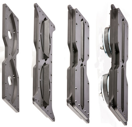
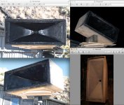
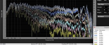
The SynTripP is designed as a two-part horn, the second portion was not attached in the following tests, and the woofer's ports have not been cut in the horn yet, so comparisons of the various stages of development can be made. Testing was done outdoors with the bottom of the enclosure a bit over two meters off the ground, test mic at two meters from the horn mouth, using Smaart with the FFT set to 32K, providing a resolution of 1.5 Hz. The magnitude response graphs below show a lot more "grass" (peak and dip detail) than the highly smoothed "marketing graphs" we usually see.
An example of how smooth the graphs can be made to look is in post #6 here:
http://www.diyaudio.com/forums/multi-way/236037-dirty-dozen-line-array.html
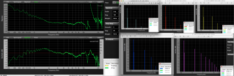
The SynTripP HF horn driven with the 16 ohm Celestion CDX14-3050 has a very extended response, +/-6 dB from 460 Hz to 17,000 Hz. Like most 3" diaphragm drivers, the CDX14-3050 has some "rough spots" in the VHF response, in this case a deep dip at 12,000 Hz, followed by a small peak at 13,680 Hz. Although the 12,000 Hz dip is probably not completely correctable with EQ, it is preferable to the sharp breakup peaks many other large diaphragm drivers have in that range, which even after correction with narrow band EQ tend to sound "spitty" or "splashy".
Other than the narrow VHF glitch, the response stays within a +/-2 dB window with an even gradual decline of 9 dB over the decade of 1600 to 16000 Hz. The equalization used to achieve the response for polar testing used five filters, a -5 dB cut and 4 dB boost being the largest. Did not spend much time on the EQ, as the cabinet will be going through several more test and listening evaluations as it nears completion.
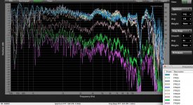
The SynTripP uses a 86 x 36 degree waveguide, the wall angles of the conical horn determine the overall dispersion pattern, though driver phase plug and exit dimensions tend to mess up dispersion to some extent in the upper range where the tiny HF wavelengths are multiples of the driver's throat dimensions. "Pattern flip", the frequency at which the vertical dispersion becomes wider than the horizontal, occurs around 1000 Hz, as expected with the short vertical dimension. Waveguides like this sacrifice some sensitivity for even response, the HF 1w 1m sensitivity at 1600 Hz is 111.4 dB, actual measured response was 105.4 dB at 2 meters with a 4 volt sine wave input. The "0 dB" line on the charts is 4.7 dB below raw response at 1600 Hz, so the HF sensitivity averages about 106.7 dB 1w 1m equivalent.
After reading Earl Geddes' recent article:
http://gedlee.azurewebsites.net/downloads/On Measureing loudspeakers.pdf
This observation was of interest:
"I occasionally look at the vertical, but not that often as I don’t find anything surprising or interesting. (Except in cases where I might suspect bad things to happen based on the design and then I usually find them - i.e. across the diagonal of a
rectangular waveguide."
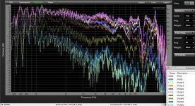
In my line of work providing sound reinforcement for live bands, both the horizontal and vertical response of loudspeakers are quite important, but had never really considered the diagonal response of rectangular horns (which I have used almost exclusively) separately. Being curious as to what "bad things might happen" also measured the SynTripP across the diagonal, as well as horizontally and vertically. The measurements show the diagonal polars are a bit more consistent in the off axis level reduction in the high frequency coverage compared to the horizontal, but show a bit of "waist-banding" (coverage that gets narrower, then widens back out) in a few frequency regions, though not to an extent that they would be apparent in any normal listening environment. Some of the differences may have been due to the test conditions, the diagonal measurement required propping the cabinet up, leaving a wedge shaped cavity between the cabinet bottom and the turntable.
The horizontal and vertical patterns of the SynTripP are quite consistent, the grill frame using half again the angle of the 86 x 36 degree waveguide seem to be effective both in reducing diffraction and waist-banding. There was no fabric in the frame for these tests, the fabric will fill in the gaps that can be seen around the frame in the test photos. It will be interesting to see how much effect the second portion of the horn will have when it is added.
The CDX14-3050 is rated for 75 watts, using the AES compressed pink noise signal with 6 dB crest factor, so probably is safe with no more than about 37.5 watts using a sine wave signal, as the sine wave's 3 dB crest factor presents double the average power of the AES signal. The SynTripP design uses 10" woofers, which require the HF driver to go lower than in typical designs. The woofer's bandpass output in the 600 Hz acoustic crossover range may be in excess of 125 dB at one meter, so distortion tests were conducted to see at what level the HF driver output exceeded 10% distortion, which at the relatively low output level is a likely indicator that excursion is getting near the point where the diaphragm may contact the phase plug.
The 600 Hz one meter equivalent at 1 watt produced 104 dB with 4.5% Harmonic Distortion, at 2 watts 107.1 dB with 5.6%, 4w 110.2 dB with 7.9%, 8w 113.4dB with 11.2%, and the final test at 16 watts produced 17.8% HD at 116.8 dB SPL. Another doubling of power would be close to the thermal limit of the driver, and likely would hammer the diaphragm against the phase plug- no matter your opinion regarding audibility of distortion, that noise is unmistakable and generally shortens the diaphragm's life span considerably, if not instantly.
To put those figures in perspective, note that it only took 1w 1m for the SynTripP to produce 111.4 dB at 1600 Hz with only 1.1% HD.
I expect the acoustic crossover will end up allowing the HF electrical crossover to be quite a bit higher than 600 Hz, so the 3" diaphragm HF driver should be "clean" at least to the woofer's low frequency output level.
Now that the HF portion is complete, next phase of the project, making the 10" driver volume reducer cones, and then testing various port sizes and shapes- and seeing what effect they have on HF response.
Art
Attachments
-
 SynTripP Polar Test.jpg107.8 KB · Views: 968
 -
 STP Raw&HD.png376.1 KB · Views: 964
 -
 SynTripP horizontal.jpg175.5 KB · Views: 899
 -
 SynTripP Vertical .jpg172.7 KB · Views: 891
 -
 SynTripP 10:14:14 Tests.png107.8 KB · Views: 875
 -
 SynTripP EQ .jpg82.2 KB · Views: 283
 -
 SynTripP Diagonal.jpg190.1 KB · Views: 291
The 600 Hz one meter equivalent at 1 watt produced 104 dB with 4.5% Harmonic Distortion, at 2 watts 107.1 dB with 5.6%, 4w 110.2 dB with 7.9%, 8w 113.4dB with 11.2%, and the final test at 16 watts produced 17.8% HD at 116.8 dB SPL. Another doubling of power would be close to the thermal limit of the driver, and likely would hammer the diaphragm against the phase plug- no matter your opinion regarding audibility of distortion, that noise is unmistakable and generally shortens the diaphragm's life span considerably, if not instantly.
To put those figures in perspective, note that it only took 1w 1m for the SynTripP to produce 111.4 dB at 1600 Hz with only 1.1% HD.
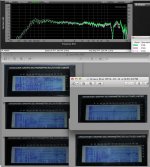
Are these typical harmonic distortion levels for this driver? It seems a bit high to me and I wonder if it is higher than usual, perhaps cabinet wall vibrations may be contributing. As an example here is the HD before and after I quelled the panel vibrations with some constrained layer damping (CLD) using a layer of latex caulking and second layer of foam core in my tractrix.
Before CLD:
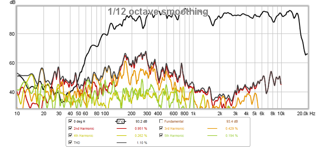
After CLD:
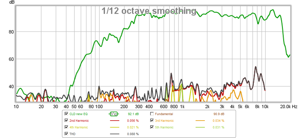
The HD is about 0.2% to 0.5% at 93dB after the CLD was applied. More info here: http://www.diyaudio.com/forums/full-range/259293-prv-5mr450-ndy-fast-applications-13.html#post4036324
- Status
- This old topic is closed. If you want to reopen this topic, contact a moderator using the "Report Post" button.
- Home
- Loudspeakers
- Multi-Way
- Synergy Tripp 10"