In the mean time I looked into simulation and I see that the 80V version
has a very restrictive clamping level for the COMP signal, which clearly adds strong distortion at high levels.
This was necessary to keep it stable even without zobel.
In case the zobel is in place (not too far away...) you can change R4 from jumper to 330 Ohms. Please really make sure that you have the zobel in place before increasing R4.
Until a few minutes ago I was also wondering why your switching frequency is between 350...400kHz, while I had designed the 80V versions for approx. 250..300kHz.
..now I understood that you are using a 15uH choke instead 33uH.

Better do not change R4 from zero to 330 Ohms before we have readjusted the loop gain of your design to less critical values.
Without diodes between rails and output any undesired instabilities really can give headache.
Please note: Post filter feedback systems are much less forgiving vs errors in the frequency compensation. In case of instabilities the system typically will go into high power resonance with the filter. And it is hard to find the right values by trial and error without theoretic analysis.
Defects are likely to give deep frustrations.
Somehow I am not sure if the design on your desk is really the same which I am trying to track and analyse with simulations.
In order to analyse loop stability and also to support on distortions I would need to know if you have further changes in the output filter or zobel values (L1,C24, C25, C26, R38, C23) . Also if you change anything with R1, C1, R6, R8, R9, R10, R12, C2, C4, C5, C6, C7,Poti, R3,R4,R5. So far I am assuming the values which you had posted in red color. If nothing posted I am assuming the values like in the original BOM. And from analysis with these values I have to tell that you are living on the edge with L1 = 15uH. More than factor two vs. 33uH kills all phase margin.
..hope still living on the edge and not yet burned...
..now I understood that you are using a 15uH choke instead 33uH.
Take care, this does not just change the oscillation frequency. It messes completely the frequency compensation. From theory your design is close to instability even with zobel.1D31A-150MC.
Better do not change R4 from zero to 330 Ohms before we have readjusted the loop gain of your design to less critical values.
Without diodes between rails and output any undesired instabilities really can give headache.
Please note: Post filter feedback systems are much less forgiving vs errors in the frequency compensation. In case of instabilities the system typically will go into high power resonance with the filter. And it is hard to find the right values by trial and error without theoretic analysis.
Defects are likely to give deep frustrations.
Somehow I am not sure if the design on your desk is really the same which I am trying to track and analyse with simulations.
In order to analyse loop stability and also to support on distortions I would need to know if you have further changes in the output filter or zobel values (L1,C24, C25, C26, R38, C23) . Also if you change anything with R1, C1, R6, R8, R9, R10, R12, C2, C4, C5, C6, C7,Poti, R3,R4,R5. So far I am assuming the values which you had posted in red color. If nothing posted I am assuming the values like in the original BOM. And from analysis with these values I have to tell that you are living on the edge with L1 = 15uH. More than factor two vs. 33uH kills all phase margin.
..hope still living on the edge and not yet burned...
Last edited:
D
Deleted member 148505
Hi Choco, here are the values that I'm using. Haven't encountered instability since I'm using it in mono mode. Also got no abnormal heating. On THD measurements, there is rising noise floor on high frequencies on high power output.
L1 = 15uH
C24 + C25 + C26 = 680nf
R38 = 2.2 ohms
C23 = 330nf
C1, C6 = 100pf
C2, C5 = 10nf
C4, C7 = 1nf
Pot1 = 1K
R9 = 150 ohms
R3, R5 = 1.8K
R4 = 0 ohm
R6 = 150 ohms
R7 = 39K
R8 = 1.8K
R10 = 2.7K
R12 = 1.5K
Regards,
Lester
L1 = 15uH
C24 + C25 + C26 = 680nf
R38 = 2.2 ohms
C23 = 330nf
C1, C6 = 100pf
C2, C5 = 10nf
C4, C7 = 1nf
Pot1 = 1K
R9 = 150 ohms
R3, R5 = 1.8K
R4 = 0 ohm
R6 = 150 ohms
R7 = 39K
R8 = 1.8K
R10 = 2.7K
R12 = 1.5K
Regards,
Lester
Hi Lester,
glad to hear that your amp is living well, while living on the edge.
My concerns are already for mono, even without the additional potential issues in multichannel arrangements.
Growing HF noise floor at high power.
From theory this is a normal effect and I have obeserved this in all class D amps, it is more a question how much the noise floor grows.
Do you have numbers how much worsening you are getting?
Typically this is strongly linked to layout. Furtheron designs with high loop gain are more demanding to get the details right. Not sure if also the COMP clamping limit (R4 setting) might show influence.
I guess you wish to use 15uH (because of size?) and also target a switching frequency around 350kHz...400kHz - right?
Please confirm or correct.
According to your feedback, I will check wich other values should be adjusted in order to get back correct design margin in terms of design stability and also avoiding the high power distortions caused be the COMP clamping.
Note:
IMHO 350kHz..400kHz is already heavy stress for IRFB4227 running into 4R from +/-80V, but I think you already have experience with your power stages. I am a switching losses SOA-coward in this regard...
It's up to you what you dare or not.
D
Deleted member 148505
Hi Choco,
I don't have the THD measurements yet, maybe this weekend i'll post it.
I already ordered 2pcs 15uH 1D31A, before I noticed that the 80V BOM uses 33uH, so I just used the 15uH in my build. Though I wish the inductor value is 22uH as I have many stocks of it
Yes usually I use 285khz to 330khz for builds using IRFB4227.
Thanks,
Lester
Ok, I will check to adjust the design for 22uH and approx. 300kHz and proper phase margin and lower distortion also at high levels... Though I wish the inductor value is 22uH as I have many stocks of it
Yes usually I use 285khz to 330khz for builds using IRFB4227.
I think I can post it at the weekend, or may be even tomorrow.
Some good news.
While reworking my simulation and double checking values which you had posted I found that in my previous simulation had mixed gain parameters of various permuations 80V, 53V, 33uH, 15uH.....
After correction, the set up with the values which you have posted is not that critical as it appeared first. Sorry for panic. Nevertheless, increasing R4 bears the risk of instability in this setup, but also in my original design.
Furtheron simulation clearly shows a massive improvement of distortions at high power with a less restrictive COMP clamping (R4).
So I definitely should check for an improved version, which allows less restrictive COMP clamping.
And I think/hope that I can settle this new version in a way that it
also serves your requested 22uH / 300kHz.
I'm affraid I've still some questions.
It's about the regulators used on the gainboard. What are the diodes d103-d104 for ? Protection ? But there isn't much capacitance at the output ?
And what about r112-113 ? They seem to raise the supply impedance quite a bit. Are they there to prevent oscillation of q1, q2 ?
Thanks for any pointers.
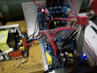
Things are slowly taking shape pcb wise.

hi 00940 and jlester . nice work guys
please post or email to me the correct working eagle files which are .sch and .brd put them in a zip folder . thanks guyz
Last edited:
D
Deleted member 148505
Some good news.
While reworking my simulation and double checking values which you had posted I found that in my previous simulation had mixed gain parameters of various permuations 80V, 53V, 33uH, 15uH.....
After correction, the set up with the values which you have posted is not that critical as it appeared first. Sorry for panic. Nevertheless, increasing R4 bears the risk of instability in this setup, but also in my original design.
Furtheron simulation clearly shows a massive improvement of distortions at high power with a less restrictive COMP clamping (R4).
So I definitely should check for an improved version, which allows less restrictive COMP clamping.
And I think/hope that I can settle this new version in a way that it
also serves your requested 22uH / 300kHz.
Nice, I haven't tried changing any values yet, but I don't have stock of 330 ohms 0805 SMD, i'll try 200 ohms for R4 first, change o/p mosfets to IRFB4227 and DT preset to DT4. And will remeasure. Expecting for 0.5% THD at levels >= 200W..
hi 00940 and jlester . nice work guys
Sorry I'll only share the gerber and not the development files.
On my prototype board, 2 electro caps have wrong polarity so I will rework it, i'll also add onboard zobel.
Also the onboard preamp adds around 10 to 15db of noise floor so if anyone wants to omit it in the final design, i will remove it.
Output hiss is low. When you put your ear on the tweeter the hiss is very faint, way less audible than regular IRAUDAMP7 clones.
D
Deleted member 148505
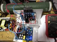
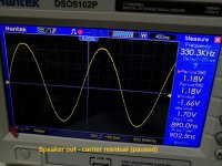
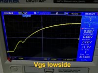
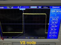
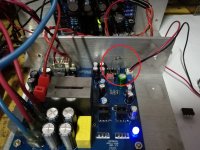
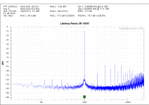
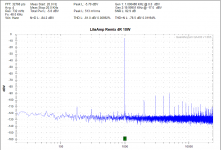
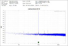
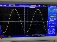
Here are some scope shots with IRFB4227. The mosfets are not getting hot even after some short burst 100W THD tests on my QA400.
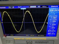
What I noticed is that in carrier residual (see 3rd pic), there are some random noise that is riding the carrier, but there are no blips!. Also the residual is kinda high 1.18Vrms
I used Abletec SMPS +/-53V on all measurements. Aux supplies are powered by linear regulator.
What I noticed is that in carrier residual (see 3rd pic), there are some random noise that is riding the carrier, but there are no blips!. Also the residual is kinda high 1.18Vrms
I used Abletec SMPS +/-53V on all measurements. Aux supplies are powered by linear regulator.
Attachments

Last edited by a moderator:
D
Deleted member 148505
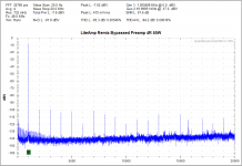
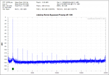
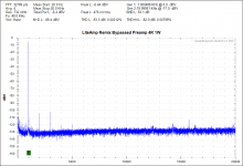
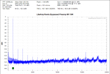
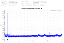
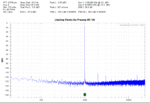
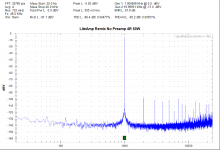
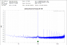
Here are some quick THD measurements when Preamp is bypassed. If there is no preamp, my QA400 generator + THAT1646 which is powered by +/-10V DC (from boost converter) runs out of juice to drive the liteamp so the measurements are up to 50W and 10W only.
I believe if my QA400 interface is powered by batteries, the measurements, will slightly improve.
I believe if my QA400 interface is powered by batteries, the measurements, will slightly improve.
Attachments
D
Deleted member 148505
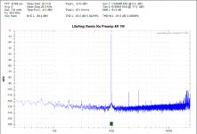
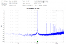
Ok so my interface for QA400 has a differential input, so I grounded it and got better THD results. Attached pic for my liteamp with bypassed preamp.
Attachments
D
Deleted member 148505
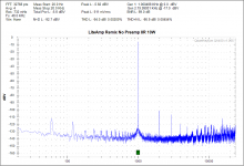
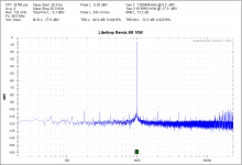
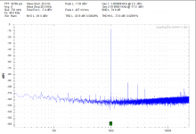
Attached THD measurements using built in preamp, opamp used is LME49720.
I don't know if the high frequency noise floor fluctuations are just random interference from test setup or is inherent and due to my PCB layout.
I don't know if the high frequency noise floor fluctuations are just random interference from test setup or is inherent and due to my PCB layout.
Attachments
Hi Lester,
thanks for posting the diagrams.
IMHO that‘s already better than many PA amps, however I agree that the strong increase
of distortion already at medium power levels is not nice.
Here a version which should serve needs better.
In this design the carrier signal at COMP is smaller than in the earlier versions, ==> more
headroom until the clamping kicks in. Further increased headroom by setting R4 to 200R like
you already did for the previous version.
22uH vs 15uH also reduces the amount of output ripple (if adjusted to same frequency).
L1 = 15uH ==> change to 22uH
C24 + C25 + C26 = 680nF Ok
R38 = 2.2 ohms Ok
C23 = 330nF Ok
C1=100pF Ok
C6 = 100pF ==> change to 220pF (for experiments you can parallel another 100pF)
C2, C5 = 10nF ==> change to 22nF (for experiments you can parallel another 10nF from bottom side)
C4, C7 = 1nF Ok
Pot1 = 1K 500R is sufficient (good starting point is R9+Pot=150 Ohms)
R9 = 150 ohms ==> change to 82 Ohms
R3, R5 = 1.8K Ok
R4 = 0 ohm ==> change to 200 Ohms
R6 = 150 ohms Ok
R7 = 39K Ok
R8 = 1.8K Ok
R10 = 2.7K Ok
R12 = 1.5K Ok
22uH vs 15uH also reduces the amount of output ripple.
About the noise of your preamp:
Typically the noise is resulting from four effects. Voltage gain of the circuit, voltage noise of the OP amp, current noise of the OP multiplied with the concerned network impedance, voltage noise of the resistors. In order to give more detailed hints you would need to disclose the full circuitry.
Random noise on the output carrier:
This is looking like a wiring topic and visibility likely will depend on where you put the probes.
If you put the probes right at the output terminal of your PCB, I would guess that it turns
small or even unvisible.
In any case if this a fluctuating phenomenon it could be the reason for your fluctuating noise floor.
D
Deleted member 148505
Hi Choco, thank you for the updates so that mid power measurements will be better. If 1uf for output filter cap is used, are the values still ok? I have lots of it. I only ordered 2pcs 680nf.
On my posts #590 onwards, I already changed R4 to 200R (my only available 0805 SMD near 330R) and changed output mosfets to IRFB4227. 10W and below measurements drastically improved. Noise floor on bypassed preamp is excellent, better than most class-ab's that I've measured.
Attached schem with current values which I've already measured and posted on my previous, and the new proposed values. I also want to slightly increase the gain of preamp.
@All
Not planning to sell this, I just want to try SMD parts (my first SMD layout actually) and try my new style of layout if it'll work.
Attachments
On my posts #590 onwards, I already changed R4 to 200R (my only available 0805 SMD near 330R) and changed output mosfets to IRFB4227. 10W and below measurements drastically improved. Noise floor on bypassed preamp is excellent, better than most class-ab's that I've measured.
Yes, I also think your results are already now respectable.

But I think the structure of the LiteAmp has the potential for even better behavior (especially regarding distortion in mid power range), so I started to dig into simulation again. Let's see how far we can bring your amp
. I will also have a look to your 1uF request.
Hi Lester,
here the proposal for the output filter 22uH and 1uF:
L1 = 22uH
C24 + C25 + C26 = 1uF
R38 = 2.2 ohms
C23 = 330nF
C1=100pF
C6 = 100pF like initial version
C2, C5 = 22nF
C4, C7 = 1nF
Pot1 = 500R Good starting point is R9+Pot=200..300Ohms
R9 = 100 Ohms
R3, R5 = 1.8K
R4 = 200 Ohms
R6 = 820 Ohms Yes, big step. If not available, you can parallel two 1800 Ohms in backpack style.
R7 = 39K
R8 = 1.8K
R10 = 2.7K
R12 = 1.5K
In general poti settings towards lowest frequency let expect worse mid power distortion.
D
Deleted member 148505
Hi Choco, thank you for providing new values, I replaced output filter to 22uH + 1uF, R6 to paralleled 1.8K. C2, C5 = paralleled 10nF
Set osc freq to 300kHz (when measuring THD).
THD has increased, when preamp is bypassed, THD is also the same (but lower noise floor), also I forgot to mention earlier that the gain is very low when there is no preamp. With 4.1Vrms input, the output is only around 11.8Vrms.
Anyways, I prefer a more stable amp than having a low distortion while hanging on the edge of stability.
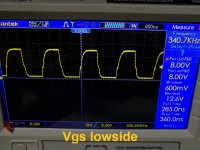
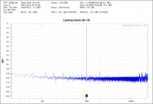
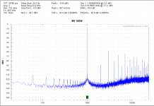
Attached picture which shows the location of probe used for THD and oscilloscope measurements, carrier residual when being set to 330khz and attached to 8 ohms load, and THD at 1W and 100W.
Set osc freq to 300kHz (when measuring THD).
THD has increased, when preamp is bypassed, THD is also the same (but lower noise floor), also I forgot to mention earlier that the gain is very low when there is no preamp. With 4.1Vrms input, the output is only around 11.8Vrms.
Anyways, I prefer a more stable amp than having a low distortion while hanging on the edge of stability.
Attached picture which shows the location of probe used for THD and oscilloscope measurements, carrier residual when being set to 330khz and attached to 8 ohms load, and THD at 1W and 100W.
Attachments
The voltage gain without preamp should be slightly more than factor 9.... I forgot to mention earlier that the gain is very low when there is no preamp. With 4.1Vrms input, the output is only around 11.8Vrms.
If you get less than factor three, then there must be a hidden error – either in the measurement or in the proto.
First point to double check would be R10 and R12, massive value errors here would lead to your described lower
gain and still would allow overall reasonable performance as visible in your measurements.
Regarding distortion at 100W/8R from +/-53V:
With respect to the 53V rails this is already a high power level, because the modulator already has to
modulate the duty cycle in a range between 25 to 75%.
Nevertheless – for this condition I am seeing a sweet spot.
While for a setting of R9+Pot=200 Ohms also my simulation is showing similar values like your results,
a setting of R9+Pot=150 Ohms should bring roughly 10db improvement ==> Resulting in a THD around 0.1%.
I cannot tell if this 150 Ohms is a general sweet spot for this amp version, but most likely R9+Pot=150 Ohms
will also perform well in mid and low power operating points.
Unfortunately trying to predict distortion values below 0.1% with my simulation is just a sort of gambling.
==> Have a look to R9+Pot=150 Ohms at 100W/8R +/-53V and if this brings an improvement similar to simulation, then stick to 150 Ohms
Furtheron then all further improvements are possible only by real life fine tuning. This is especially valid for the low power operating
points with THD far below anything my simulation could properly predict.
Note: In my simulation I used a dead time of 65ns which would correspond to DT3 of the IRS2092.
Last edited:
- Home
- Amplifiers
- Class D
- SystemD LiteAmp