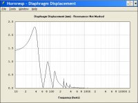
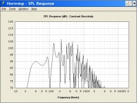
Last but not least, here's the most interesting graph of all. It's the exact same woofer, in a tapped horn, with a volume comparable to the bandpass.
We see two things:
1: The efficiency is slightly lower than the bandpass.
2: The Tapped Horn plays lower
In other words, it confirms what I'm hearing.
This is what I hate about physics! No free lunch DAMMIT!!!
We see two things:
1: The efficiency is slightly lower than the bandpass.
2: The Tapped Horn plays lower
In other words, it confirms what I'm hearing.
This is what I hate about physics! No free lunch DAMMIT!!!
Attachments
Hi Guys
While it is possible to make a TH that has a response that looks like a Band pass speaker, it is also possible to make one that doesn’t look like one.
For example, look at the measured response of these TH’s measured in half space.
http://www.danleysoundlabs.com/pdf/TH 215 Spec Sheet.PDF
http://www.danleysoundlabs.com/pdf/TH MINI Spec Sheet.PDF
http://www.danleysoundlabs.com/pdf/TH 115 Spec Sheet.PDF
One can get an idea what the TH can do so far as sensitivity compared to a normally loaded driver when you consider that the TH-115 has a 15tbx100 driver for example.
To the degree the sensitivity is increased, one see’s a corresponding reduction of excursion for a given SPL.
I have never seen a Bandpass alignment that could give that much gain over the direct radiator condition while also having that wide a Bandwidth.
As one can see, there is no “low pass” corner visible in any of these TH’s; at least in the region one would expect one from a normal Band pass system (all speakers are a band pass system in one way of looking)
Also, there are some acoustical differences too.
While it probably wouldn’t matter at “living room” sound levels, most of our stuff spends its life at a significant power level so how it behaves “loud” is very important.
Theses TH’s are all based on a quarter wl resonator, at the lowest mode (the low corner) there is a pressure maximum where the driver is and Velocity maximum at the exit.
In an enclosure using a Vent / Helmholtz resonator, one finds that the vent is the velocity maximum and so the response changes significantly with level due to port non-linearity.
At concert levels it is often difficult to impossible to make a port large enough to keep its velocity / change in response to an acceptable level. Then, with a large port one has to deal with organ pipe modes.
The TH avoids that port choking problem by having a minimum of motion at the small end of the horn and not using a Helmholtz resonator to define the low end response.
Lastly, keep in mind that a driver that is ideal for a given TH is usually not the best choice in a vented or BP box with the same low corner or box volume.
In a TH, normally one wants Fs to be above the low corner for example.
Best,
Tom
Tom
All that you say might be true, but then maybe not either. I have never studied the TH and in my business (HT and Hi-Fi) I don't see a need to. Surely the TH could be an advantage if one wants a wide bandwidth at high SPLs because a bandpass can't do that. But we have been discussing subs and in this situation I see no advantage to the TH over a bandpass, in fact I see a distinct disadvantage coming from the fact that the distortion harmonics are amplified, not attenuated as they are in a band pass. But I would also contend that a bandpass at LF can always match what a TH does in output - there is no free lunch at LF.
It all comes down to the application and you and I are in different fields. I might well be drawn to a TH if I did the kinds of systems that you do, just as I am sure that you would be drawn to the bandpass in situations like mine (limited bandwidth subs).
All too often the posters here forget about this simple but fundamental difference. But it makes ALL the difference.
Oh, and your result, assuming they are correct, imply a serious modeling problem with all thats been posted before as they are nothing alike. Somebody has some work to do here to make the theory and the measurements agree.
Tom Danley said:Lastly, keep in mind that a driver that is ideal for a given TH is usually not the best choice in a vented or BP box with the same low corner or box volume.
In a TH, normally one wants Fs to be above the low corner for example.
Best,
Tom
Without a doubt, this is one of the most intriguing aspects of the tapped horn. For instance, I can take a sub driver that would give excellent output in a vented or bandpass enclosure down to 30hz, then put it in a tapped horn, only to find I get TOO MUCH low bass. Yesterday I tried half a dozen designs using a woofer with an FS of 27hz, and most of them wound up playing TOO LOW, well into the teens.
Have you ever considered licensing the tapped horn for use in car audio? There's a few aspects of it that make it ideal:
1 - Car audio guys love flashy enclosures, which is why they frequently mount the drivers INVERTED in sealed boxes, to show off the basket. Naturally, the basket on a TH is exposed.
2 - Exposing the basket should improve power handling right?
3 - Because a driver with a high FS and a high QTS works very well in a tapped horn, I have a hunch that you could make a tapped horn for a car that had an F3 in the 50s when measured outside, but would extend to 20hz thanks to cabin gain. Based on that, an inexpensive 5" or 6" woofer would make a fine driver in a TH intended for a car.
From what Tom has shown, the simulations aren't very accurate.
When I look at Tom's data, it looks classic dual ported bandpass at LF to me. There are obviously two resonances in the impedance curve and I'll bet that a dual bandpass box tuned to these same frequencies with the same driver would produce the same LF output.
When I look at Tom's data, it looks classic dual ported bandpass at LF to me. There are obviously two resonances in the impedance curve and I'll bet that a dual bandpass box tuned to these same frequencies with the same driver would produce the same LF output.
Hi Earl, all
Well, horns and Tapped horns normally also have peaks and dips in there operating range, unless the efficiency is very high.
Like you said , we are aiming at different markets, different size rooms etc but I would think what we both want to hear “ in a perfect world” would be pretty similar.
So far as how a tapped horn works / is it a band pass alignment?, your in a better position to analyze it mathematically than me, but the lack of a “low pass” corner and means the gain that results from a high pass and low pass filters close together (band pass effect) is not present. Where does the gain over a direct radiator come from then?
I would say that while horns or “tapered pipes” have some similar properties to a Helmholtz resonator , there are also differences. For example, a woofer driving a Helmholtz resonator “on tune” acts as an inverter, while a quarter wave stub produces a motional transformation but exhibits half the phase shift (90 degrees).
Also, where a Helmholtz resonator has one primary resonance, a “tapered pipe” has a number of them and alternate between pressure max and velocity max, in a horn that’s “large enough” radiation resistance makes them much less visible or even invisible.
If one made a vented box with the same low corner as a TH-115 or TH-215, one finds it has more phase shift associated with its low corner too.
Consider the Acoustic phase measured on the TH-115 or TH-215 (which appears to be inverted electrically in the test setup here) associated with the low corner .
Generally, for a given low corner, this results in less measured Group Delay too.
This reduced (phase, GD) may also suggest it is not a traditional BP speaker.
I have built a few simple band pass systems in the past, mostly with passive radiators but haven’t tried any lately, I have always leaned towards horns due to the output requirements.
I would be curious what a BP system would look like if one fixed the sensitivity low corner and size as the boundaries.
As the TH-115 has a known driver (15tbx100) and has been carefully measured outdoors, that might be a good reference.
It has an exterior volume of 420 Ltrs, is –2dB at 38Hz and has a sensitivity of about 105 dB 1W/1M below 70Hz.
The measured response and impedance curve is on the data sheet.
Alternately, the TH-215 has two purpose built drivers, has an outside volume of 505Ltrs, a sensitivity of 102dB 1W/1M and is –3dB at 28Hz.
Anyway, if you or one of you other guys feels like crunching some numbers, I’d be curious to see what it takes in a BP speaker to get this low corner, enclosure volume and sensitivity with any realistic “low pass” corner.
Is there an acoustic B.P. analogue for a Tapped Horn TH-115 or TH-215?
I don’t know if there is a free lunch in it or not, those are so rare it’s not worth looking for them or worrying about, but it has allowed me to make products that I couldn’t have made otherwise.
It will be interesting to see how easy it is to equal the TH-115 or TH-215 with a BP alignment.
Best,
Tom Danley
Tom
The problem is comparison. I can model BP, but not TH. You have measurements of a TH but not a BP. How to compare?
From your impedance curves the "gain" is obvious from acoustic loading driving the cone velocity to zero in several places (i.e. low electrical impedance.) This is exactly how the BP gets its gain.
As to the 1/4 wave tube being 90 instead of 180, this is only true above the first resonance, which will be the resonance of the lumped mass of air in the tube against the driver (or more appropriately the small volume of air in front of the driver). This is why compression drivers have two impedance peaks instead of one. Only a flat piston on a tube of equal area would not show this effect.
I just cannot see how a twenty to thirty foot wavelength knows that a horn is a horn and not just a duct. Compared to this wavelength the cross sectional variations are miniscule. The horn is a duct at the lower edge, the system acts as a dual bandpass at these lowest frequencies and then as the normal BP would fall off, the 1/4 wave resonances add to the response to bring the output back up. I see this all the time when I do bandpass designs where the ports get too long. The Bose wave cannon is really the ultimate design in this configuration (no credit to Bose, its an old idea that they simply resurected.)
Hi guys, from my rank amateur naive perspective, it seems like you are basically saying the same thing in different words, kind of.
Yes, a tapped horn can be compared to a 6th (or 7th or 8th?) order bandpass with (too long) ports quite easily, and in a similar sized package I assume you could come up with a high order bandpass that affords either the efficiency OR the wide bandwidth of the tapped horn. (I don't think this point is in diagreement? - maybe I'm wrong)
In the case of the tapped horn, the length and shape of the taper (or ports, if compared to a bandpass) and the driver position are carefully chosen such that at least one of the lowest pipe resonances are used to good effect to keep the response even over a wider than normal bandwidth (when compared to high order bandpass of the same volume) and overall tuning, whereas any resonances above the fundamental in a bandpass would only be waste product. Thus, the tapped horn requires no stuffing to achieve high efficiency over a relatively wide bandwidth (when compared to high order bandpass of the same volume). And as a side benefit the tapped horn does not exhibit any port compression, due to the nature of the "port".
Please excuse my inherent ignorance due to lack of experience, but like I said, from my perspective it sounds like you guys are saying the same thing in different words.
Ok, so maybe everyone agrees on everything now, or (probably much more likely) I've offended two of our very important senior members (I'm talking about acrued knowledge here, not senior as in old).
So I will sit back and be quiet now, as I greatly enjoy reading the posts from each of you and seriously do not care to offend either of you.
So I will sit back and be quiet now, as I greatly enjoy reading the posts from each of you and seriously do not care to offend either of you.
just a guy said:
Please excuse my inherent ignorance due to lack of experience, but like I said, from my perspective it sounds like you guys are saying the same thing in different words.
I don't think that we are saying the same thing, but I don't think that we disagree either. We are looking at the problem from different perspectives and noting how and why certain atributes of one over the other might apply. This is what engineers do. Good engineers don't usually disgaree on the fundamentals, but almost always disagree on the tradeoffs. It's those details that are hard to quantify that one engineer may have a "feeling" that one approach is better and another one another.
Tom's asset is his practical experience and mine is my expertise at the theory. These two things can be as similar as they can be vastly different, with neither one being right or wrong. Things "gell" when the two agree and there is more to learn when they don't.
just a guy said:Ok, so maybe everyone agrees on everything now, or (probably much more likely) I've offended two of our very important senior members (I'm talking about acrued knowledge here, not senior as in old).
So I will sit back and be quiet now, as I greatly enjoy reading the posts from each of you and seriously do not care to offend either of you.
I don't think that you offended anyone, and I am sure that you didn't offend Tom or me. Its a holiday weekend, and I don't spend as much time at my computer as normal.
Tom Danley said:I would be curious what a BP system would look like if one fixed the sensitivity low corner and size as the boundaries.
As the TH-115 has a known driver (15tbx100) and has been carefully measured outdoors, that might be a good reference.
It has an exterior volume of 420 Ltrs, is –2dB at 38Hz and has a sensitivity of about 105 dB 1W/1M below 70Hz.
The measured response and impedance curve is on the data sheet.
Alternately, the TH-215 has two purpose built drivers, has an outside volume of 505Ltrs, a sensitivity of 102dB 1W/1M and is –3dB at 28Hz.
Anyway, if you or one of you other guys feels like crunching some numbers, I’d be curious to see what it takes in a BP speaker to get this low corner, enclosure volume and sensitivity with any realistic “low pass” corner.
Is there an acoustic B.P. analogue for a Tapped Horn TH-115 or TH-215?
I don’t know if there is a free lunch in it or not, those are so rare it’s not worth looking for them or worrying about, but it has allowed me to make products that I couldn’t have made otherwise.
It will be interesting to see how easy it is to equal the TH-115 or TH-215 with a BP alignment.
Best,
Tom Danley
I've been crunching the numbers on bandpass boxes for well over a decade, and was quite excited to try a tapped horn as soon as I could. Based on my experience with this, here are a few observations:
- For a given box size, the efficiency of all alignments are quite similar. For instance, a bandpass and a vented half nearly the same response in the lower octaves if the F3 is comparable.
- You can shrink a tapped horn down dramatically. For example, the 15TBX100 can be used in a tapped horn that's one quarter the size of your TH115, IF you're willing to sacrifice efficiency.
- When the tapped horn is shrunked down to a dramtically smaller footprint, then you discover that a plain ol' bandpass offers an efficiency that's comparable - and a lot easier to build.
This morning I crunched the numbers on the 15TBX100 for a couple of hours, and ran into a couple of challenges. The first challenge is that putting the 15TBX100 in a bandpass box that's 10 cubic feet doesn't work too well. It's just needlessly large. On the other hand, you can shrink the TH 115 into a package that's comparable in size to a proper bandpass, but then the efficiency drops. It's quite a catch-22!
gedlee said:Tom
The problem is comparison. I can model BP, but not TH. You have measurements of a TH but not a BP. How to compare?
From your impedance curves the "gain" is obvious from acoustic loading driving the cone velocity to zero in several places (i.e. low electrical impedance.) This is exactly how the BP gets its gain.
As to the 1/4 wave tube being 90 instead of 180, this is only true above the first resonance, which will be the resonance of the lumped mass of air in the tube against the driver (or more appropriately the small volume of air in front of the driver). This is why compression drivers have two impedance peaks instead of one. Only a flat piston on a tube of equal area would not show this effect.
I just cannot see how a twenty to thirty foot wavelength knows that a horn is a horn and not just a duct. Compared to this wavelength the cross sectional variations are miniscule. The horn is a duct at the lower edge, the system acts as a dual bandpass at these lowest frequencies and then as the normal BP would fall off, the 1/4 wave resonances add to the response to bring the output back up. I see this all the time when I do bandpass designs where the ports get too long. The Bose wave cannon is really the ultimate design in this configuration (no credit to Bose, its an old idea that they simply resurected.)
Mc Bean's hornresp can model a number of enclosures that aren't documented.
For example, it can model single reflex bandpass. Just take the volumes of S1 through S4 and set them so they're equivalent to the area of the port in a bandpass. For instance, if you're modeling a four inch port, set S1 to 79.57cm, S2 to 80.57cm, and S3 to 81.57cm. You have to stagger them very slightly to prevent a divide by zero error.
Horn response can also model dual reflex bandpass. Set the port length in the variable LPT and the area in Ap.
The greatest reason to use hornresp for bandpass is that it can model pipe resonances and reflections better than anything I've seen. It also lets you juggle a lot of variables. For example, you can define a dramatically flared port, then examine how the flare effects the tuninq frequency (it makes quite a difference actually.)
Patrick Bateman said:For instance, if you're modeling a four inch port, set S1 to 79.57cm, S2 to 80.57cm, and S3 to 81.57cm. You have to stagger them very slightly to prevent a divide by zero error.
Hi PB,
Could you please do me a big favour and post a screenprint of the Hornresp Input Parameters window for a sample set of data that generates the "divide by zero" error you are seeing. It sounds like you may have found a bug in the program, and I would really like to fix it if I can.
I assume that you are using the latest release, Product Number 1940-080823?
Thanks in anticipation.
Kind regards,
David
gedlee said:The problem is that Tom's measurements and your simulations look nothing alike. What's up with that?
I believe there's three reasons for this:
1: In the real world, the peaks predicted by horn response aren't as severe as the simulations predict. Considering the predictions indicate peaks that are a fraction of a DB wide, this isn't surprising "IRL."
2: Danley's measurements pick up an efficiency bump from being in half space. I really hope people on the main TH thread recognize this, because there are a lot of people out there who are expecting a 4cf tapped horn to play 12db louder than a vented box of comparable size, and that's NOT the case. Even Danley's white paper spells this out. This fact got lost in the main thread when everyone started doing their sims in 1/4 space and 1/8th space
3: I've been using box volumes which are dramatically smaller than Danley or the other people on the main TH thread. This yields much lower efficiency. I'm going that route because I'm using multiple small subs, instead of one big ol' "tower of power." In my home, with hardwood floors and a lot of square footage, multiple subs sounds a heck of a lot better than a single sub.
Hi, Mr Naive Amateur checking in again.
I haven't spent nearly as much time as some people here with tapped horn sims and I don't even have the new sliderific version of hornresp, but I have noticed a couple of things about the models that are typically being presented by the diy crowd.
The (commercial) tapped horn ALWAYS uses the inherent resonances to achieve a much wider than normal bandwidth. MOST of the diy tapped horns we have seen do not use the resonances specifically to enhance bandwidth for one reason or another. So most of the diy tapped horns will not have anywhere near the bandwidth of a commercial tapped horn.
The commercial tapped horn uses a driver that has significantly higher fs than line tuning, which I am almost certain is the key to the commercial tapped horn's mild and even rising response. Most diy versions have a big bump right at tuning, whereas the commercial tapped horn exhibits more of an extended bass shelf type response, so I'm pretty sure fs is key here.
The commercial tapped horns were measured outside at 10W/10M, not sure how this affects things, but it probably has some effect.
So that might help to explain a bit why diy tapped horns are not measuring as well as commercial tapped horns but...
The fact remains that my (admittedly half hearted) attemps to reverse engineer the dts-20 with the driver and drawings which I believe to be correct (or maybe just close enough) yeild sims that are not even really close in terms of response curve shape or spl output. I now see the discrepancy as multi faceted. There's a little bit of marketing inflating the peak spl numbers, a little bit of "Danley Magic" (years of experience resulting in an incredibly complex design and probably taking into consideration things diy'ers might not), a little bit of inductance, a little bit of outside measurements, and even a little bit the of the optional add-on $1000 factory preset dsp won't hurt either. I think that's why diy sims aren't looking exactly like the commercial tapped horn measurements.
But as always I could be completely wrong about any or all of this.
The problem is that Tom's measurements and your simulations look nothing alike. What's up with that?
I haven't spent nearly as much time as some people here with tapped horn sims and I don't even have the new sliderific version of hornresp, but I have noticed a couple of things about the models that are typically being presented by the diy crowd.
The (commercial) tapped horn ALWAYS uses the inherent resonances to achieve a much wider than normal bandwidth. MOST of the diy tapped horns we have seen do not use the resonances specifically to enhance bandwidth for one reason or another. So most of the diy tapped horns will not have anywhere near the bandwidth of a commercial tapped horn.
The commercial tapped horn uses a driver that has significantly higher fs than line tuning, which I am almost certain is the key to the commercial tapped horn's mild and even rising response. Most diy versions have a big bump right at tuning, whereas the commercial tapped horn exhibits more of an extended bass shelf type response, so I'm pretty sure fs is key here.
The commercial tapped horns were measured outside at 10W/10M, not sure how this affects things, but it probably has some effect.
So that might help to explain a bit why diy tapped horns are not measuring as well as commercial tapped horns but...
The fact remains that my (admittedly half hearted) attemps to reverse engineer the dts-20 with the driver and drawings which I believe to be correct (or maybe just close enough) yeild sims that are not even really close in terms of response curve shape or spl output. I now see the discrepancy as multi faceted. There's a little bit of marketing inflating the peak spl numbers, a little bit of "Danley Magic" (years of experience resulting in an incredibly complex design and probably taking into consideration things diy'ers might not), a little bit of inductance, a little bit of outside measurements, and even a little bit the of the optional add-on $1000 factory preset dsp won't hurt either. I think that's why diy sims aren't looking exactly like the commercial tapped horn measurements.
But as always I could be completely wrong about any or all of this.
- Status
- This old topic is closed. If you want to reopen this topic, contact a moderator using the "Report Post" button.
- Home
- Loudspeakers
- Subwoofers
- Tapped Horn for Dummies