just a guy said:Hi, Mr Naive Amateur checking in again.
This sounds a bit disingenuous to me.
I am never comfortable with a design that does not converge on the same answer in models and reality. There is something going on that is not understood and almost without question, this will come back and bite you in the ... .
John and all
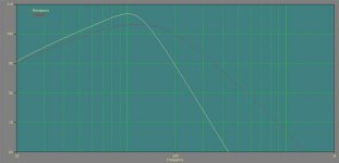
I finally got a chance to run some sub sims. Attached is a plot of the MCM driver in a bandpass box and a closed box of the same volume. The added efficiency of the bandpass is evident. What is not evident is that the cone excursion of the bandpass is lower and with its acoustic LP function the bandpass should play much louder than the closed box. This is a simple single ported design like I find work so well in my own systems. The LP filter is included at 120 Hz.
Now the problem that I have with the MCM is that its excurasion limits and thermal limits don't track each other. In other words I can't even come close to the stated excursion before the power input exceeds the spec. This is a total waste of VC real estate.
Other than that its a good driver.
I am going to use two drivers in one enclosure with one amp driving both. I should be able to do this for a very reasonable price - maybe $399 each. These are ideal broadband subs, but in a really great system I would add a single VLF subs at the very bottom end. That design is next, but the cheap MCM drivers "can't get their from here".
Attachments
Tom Danley said:
I would be curious what a BP system would look like if one fixed the sensitivity low corner and size as the boundaries.
As the TH-115 has a known driver (15tbx100) and has been carefully measured outdoors, that might be a good reference.
It has an exterior volume of 420 Ltrs, is –2dB at 38Hz and has a sensitivity of about 105 dB 1W/1M below 70Hz.
The measured response and impedance curve is on the data sheet.
Anyway, if you or one of you other guys feels like crunching some numbers, I’d be curious to see what it takes in a BP speaker to get this low corner, enclosure volume and sensitivity with any realistic “low pass” corner.
Is there an acoustic B.P. analogue for a Tapped Horn TH-115 or TH-215?
Tom Danley
gedlee said:
This sounds a bit disingenuous to me.
I am never comfortable with a design that does not converge on the same answer in models and reality. There is something going on that is not understood and almost without question, this will come back and bite you in the ... .
Hi guys,
In line with my earlier posts in this thread, I'd say that just-a-guy isn't far off the mark.
I also think "Patrick" needs to be a little more conscientious in making proclamations in regards to designs based only on a few builds and models, especially when the two don't match or deviate significantly from the intended target.
The models don't really disagree from what I'm seeing in a simple comparison to a BP6 enclosure of either separately tuned chambers or a series configuration which more closely parallels the physical layout of the TH. Just as a transmission line is akin to a ported box with added factors, the same is true of the Tapped Horn relative to loosely related bandpass designs.
In more classic use we assume the chambers to be significant in size and we assume the ports to be more simplistic and separate from the chamber's volume. These differences, along with an accounting of Q differences for various resonances pretty well explain what is observed, although I'm just making the observation, not the math behind these additional factors. Since bandpass designs or similar rely on the combination of resonances to produce the gain in sensitivity, the Q of these resonances is significant to the accuracy of the result, where the specific implementation will greatly impact those Q values.
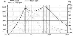
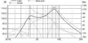
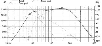
Attached are two 6th order bandpass examples, parallel and series, using the same approximate gross volume (port volume included) using large ports of 10-12" diameter where the impedance minimums are approximately matched. I only had the 8 Ohm version of the driver in my models, so I input 2W to match the drive level of the 4 Ohm version driven with 2.83V in the TH-115 measurements. The impedance minimums in the models are only slightly below 2x that of the TH115, where I have found it fairly common for this model in LspCAD to slightly over-estimate minimums. I have been building quite a few bandpass subs over the past 2 years, and the model has been as accurate as the driver parameters and assumptions made.
What you see is that the peaks of both designs are rather comparable to the sensitivity of the TH115, with a significant saddle in the response where the tapped horn has little or a much shallower saddle, with a more extended top end.
These particular models are not showing port resonances nor radiation of HF through the ports, both of which are at work and significant in the TH design.
A friend recently built up and sent me measurements of a 6th order bandpass (both chambers tuned separately to outside), where the LF chamber wasn't stuffed and used a straight, 4" diameter, flared port. In this case the 1st port resonance and an internal pathway reflection coincided, making for a very strong port resonance near 190Hz. While almost an octave above the designed HF corner of the device and where ~160Hz was >15dB down, the output of this resonance was in fact equal to the midband response of the device.
It shouldn't take much extrapolation to figure that with a much larger and longer port, this resonance, and others, could be intentionally pulled back into the operating bandwidth (departing from common practice and goals) to serve as useful output. Now taper the ports to somewhat broaden the resonance with a lower Q/ less narrow resonance, and you can see how a design might be able to fill in the saddles seen in what might otherwise be seen as over sized bandpass boxes with a peaky response.
This is of course looking at the problem from the other direction from a horn model, but being that the TH has behavior somewhere in between, this should come as no surprise. The more the chambers are tapered, and the less of a volume there is for each chamber, the more deviation there will be from this look, but it does show that the models and expectations make sense... So long as the design fits the assumptions of the model.
Attachments
Regarding the simulation vs performance of the TH (ala Danley).
In the original TH thread there was a picture of the inside of a DTS20 tapped horn (I can't find a link right now). It clearly showed two PVC pipe contraptions. They differed in length and both led toward the "dividing wall". What was not clear was whether they were in "acoustic contact" with the other chamber. I suspect they were not and that they were acting as a Helmholtz resonator. Perhaps this was done to acoustically knock down some peaks in the response. But I am only guessing.
The reason I bring this up is because it seems most of the builders are not incorporating this feature (which would probably take a good amount of fiddling to get it right). I believe this feature is also not being incorporated into the simulations either.
Although this will have little impact on the "extra" efficiency that folks are concerned about. It might play into some other differences however.
Mark
Please define what you mean by "series" and "parallel" configurations as these are not terms that I have ever used when I described bandpass enclosures.
Do you mean a resonator on each side of the driver as "parrallel"? What I call dual ported. And two resonators in "series" on one side of the driver?
gedlee said:Mark
Please define what you mean by "series" and "parallel" configurations as these are not terms that I have ever used when I described bandpass enclosures.
Do you mean a resonator on each side of the driver as "parrallel"? What I call dual ported. And two resonators in "series" on one side of the driver?
Correct Earl,
There really isn't any clear nomenclature so far as I've seen, so a little searching and a picture is worth lots of typing:
I agree that "parallel" was probably a poor choice of words, but the first system was this configuration:

The system I referred to as a 6th order series bandpass is as follows:

Hi Guys
Sorry for the absence yesterday, it was time to breath some Coal smoke.
http://www.thresheree.org/
In reading the replies and Marks plots, I would again say that a Helmholtz resonator and a resonant tube have some similarities but also have differences.
In a case like the TH-115 there is very little “rear cavity volume” only the air trapped under the cone and no obvious “front volume” so what is happening is mostly the action is from the length resonance’s.
In Marks nice BP model, one can see that there is a definite “low pass” corner and it is usually the close placement of the high pass and low pass corners that form the “band pass” gain that fills in the space between the two bumps.
These filters are the Helmholtz resonators, both are low pass filters, one for the front side and one for the rear side of the driver.
A Helmholtz resonator only has one resonance however, while a resonant tube has a “lowest mode” where there is a pressure maximum at the closed end and then a series of modes above that which alternate between velocity and pressure maximums at the driver end. A resonant tube is not an acoustic low pass filter like a Helmholtz resonator.
In a conventional bass horn, one finds the horn isn’t efficient until it is at least one half WL long, while most real horns are sized to be one quarter wl long.
One can make a quarter wave horn much more efficient if one uses a heavier / stronger driver who’s larger BL^2 / Rdc is more suited to the limited motion at the pressure maximum. On the other hand, that same driver is a poor choice everywhere above that quarter wave resonance; it is too strong, too heavy.
The Tapped horn is a way to have the driver properties effectively change, at the low cutoff, only the end radiator face “feels” the load from the quarter wave stub.
AS the frequency climbs, the other face begins to add constructively.
Without the front tap, these horns still behave like horns, it has a series of resonances, not like a BP speaker, and there isn’t a low pass filter as is normally the case with a BP system.
Adding the front tap doesn’t add a low pass corner either but when everything is right, it fills in the saddle.
The reason the Fs is best above the low cutoff is that like a conventional horn, one finds that the air in the horn acts like a capacitance who’s value increase as the frequency falls approaching the cutoff. In a conventional horn, one can choose the right driver, use an appropriate Hyperbolic expansion to tailor the shape of that curve, combined with the proper rear volume and that results in “reactance annulling”, which extends the useful low corner downward.. Here, the compliance volume conjugates the horn’s mass by producing a broadly resonant condition.
In the Tapped horn, there is no adjustable rear volume to play with but that required spring force can be had in the drivers suspension.
To answer just a guys concerns, there is no DSP used, the cabinets are driven with a fixed Voltage of 28V (100W into nominal 8Ohm load, +20dB over 1Watt) and measured at a distance of 10 Meters (-20dB from one meter).
Since most drivers begin to exhibit changes in T&S parameters due to VC heating starting between 1/8 and 1/10 rated power, this is a conservative rating.
Lastly, a thought experiment.
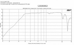
Below is a measured curve for 4X TH-115’s, each driven with 25Watts (these were with the 8Ohm driver).
The sensitivity is between 108 and 110dB 1W / 1M which places it in the 30-50% nominal efficiency range. Can one even make a BP system with that kind of sensitivity?
To me, considering the sensitivity as well as the lack of the low pass corner near the high pass corner and the absence of phase shift associated with the low pass corner and different phase shift everywhere else; makes it look a lot more like a horn than a BP system to me.
Best,
Tom Danley
Sorry for the absence yesterday, it was time to breath some Coal smoke.
http://www.thresheree.org/
In reading the replies and Marks plots, I would again say that a Helmholtz resonator and a resonant tube have some similarities but also have differences.
In a case like the TH-115 there is very little “rear cavity volume” only the air trapped under the cone and no obvious “front volume” so what is happening is mostly the action is from the length resonance’s.
In Marks nice BP model, one can see that there is a definite “low pass” corner and it is usually the close placement of the high pass and low pass corners that form the “band pass” gain that fills in the space between the two bumps.
These filters are the Helmholtz resonators, both are low pass filters, one for the front side and one for the rear side of the driver.
A Helmholtz resonator only has one resonance however, while a resonant tube has a “lowest mode” where there is a pressure maximum at the closed end and then a series of modes above that which alternate between velocity and pressure maximums at the driver end. A resonant tube is not an acoustic low pass filter like a Helmholtz resonator.
In a conventional bass horn, one finds the horn isn’t efficient until it is at least one half WL long, while most real horns are sized to be one quarter wl long.
One can make a quarter wave horn much more efficient if one uses a heavier / stronger driver who’s larger BL^2 / Rdc is more suited to the limited motion at the pressure maximum. On the other hand, that same driver is a poor choice everywhere above that quarter wave resonance; it is too strong, too heavy.
The Tapped horn is a way to have the driver properties effectively change, at the low cutoff, only the end radiator face “feels” the load from the quarter wave stub.
AS the frequency climbs, the other face begins to add constructively.
Without the front tap, these horns still behave like horns, it has a series of resonances, not like a BP speaker, and there isn’t a low pass filter as is normally the case with a BP system.
Adding the front tap doesn’t add a low pass corner either but when everything is right, it fills in the saddle.
The reason the Fs is best above the low cutoff is that like a conventional horn, one finds that the air in the horn acts like a capacitance who’s value increase as the frequency falls approaching the cutoff. In a conventional horn, one can choose the right driver, use an appropriate Hyperbolic expansion to tailor the shape of that curve, combined with the proper rear volume and that results in “reactance annulling”, which extends the useful low corner downward.. Here, the compliance volume conjugates the horn’s mass by producing a broadly resonant condition.
In the Tapped horn, there is no adjustable rear volume to play with but that required spring force can be had in the drivers suspension.
To answer just a guys concerns, there is no DSP used, the cabinets are driven with a fixed Voltage of 28V (100W into nominal 8Ohm load, +20dB over 1Watt) and measured at a distance of 10 Meters (-20dB from one meter).
Since most drivers begin to exhibit changes in T&S parameters due to VC heating starting between 1/8 and 1/10 rated power, this is a conservative rating.
Lastly, a thought experiment.
Below is a measured curve for 4X TH-115’s, each driven with 25Watts (these were with the 8Ohm driver).
The sensitivity is between 108 and 110dB 1W / 1M which places it in the 30-50% nominal efficiency range. Can one even make a BP system with that kind of sensitivity?
To me, considering the sensitivity as well as the lack of the low pass corner near the high pass corner and the absence of phase shift associated with the low pass corner and different phase shift everywhere else; makes it look a lot more like a horn than a BP system to me.
Best,
Tom Danley
Attachments
Mark Seaton said:Hi guys,
In line with my earlier posts in this thread, I'd say that just-a-guy isn't far off the mark.
I also think "Patrick" needs to be a little more conscientious in making proclamations in regards to designs based only on a few builds and models, especially when the two don't match or deviate significantly from the intended target.
The models don't really disagree from what I'm seeing in a simple comparison to a BP6 enclosure of either separately tuned chambers or a series configuration which more closely parallels the physical layout of the TH. Just as a transmission line is akin to a ported box with added factors, the same is true of the Tapped Horn relative to loosely related bandpass designs.
I don't think we disagree on anything here do we?
A few weeks ago I set out to build a set of dramatically under-sized tapped horns. If anyone wants to check my data, I posted exactly what I built. There are two tapped horns; one is in my living room, the other one is in shambles, after it fell off my deck(!)
Once completed, I was surprised to find they weren't as efficient as I'd hoped. At that point I modeled and built a bandpass box which is half the size.
I have personally built front loaded horns, tapped horns, bandpass boxes, vented boxes and sealed boxes. Based on my hands-on experience and almost two decades of study, I believe that a bandpass and a tapped horn of SIMILAR size will have comparable efficiency.
Things change when you give the tapped horn some room to breathe though! Once you quadruple the foot print, the efficiency goes up dramatically. If you try the same trick with the bandpass, it doesn't work well, because there simply aren't as many variables to play with. For instance, you can use a much larger port, but then you start suffering from port resonances in a big way.
To make a long story short, I would discourage anyone from building a tapped horn which has been dramatically undersized.
Note that I'm not discouraging anyone from building SMALL tapped horns, just UNDERSIZED tapped horns. For example, let's say your goal was to build a tapped horn that's flat to 25hz. If you had to choose between using an eight inch woofer with an FS of 31hz or a pair of six inch woofers with an FS of 50hz, I'm inclined to believe that you would get better results with a pair of sixes. Keep in mind that is CONTRARY to what you would do with almost ANY other sub box. When it comes to subwoofers, a low FS is typically a GOOD thing. As Danley noted himself, tapped horns work quite well with drivers that have relatively high FS.
gedlee said:
This sounds a bit disingenuous to me.
I am never comfortable with a design that does not converge on the same answer in models and reality. There is something going on that is not understood and almost without question, this will come back and bite you in the ... .
That greeting (Mr Naive...) was just a bit of poking fun at myself, and at the same time trying to indicate I am no expert in these matters.
Mr D has indicated on several occasions that he has modelling capabilities that can and indeed do model his tapped horns accurately. This leaves the possibility that I'm not using hornresp correctly (most probable as I didn't invest too much time into it), or TD's modelling software has intuitive features that hornresp does not have (even so the differences would probably be quite minimal), or Mr D is inputting more relevant info into his models than we are (probably probable).
Tom Danley said:
A Helmholtz resonator only has one resonance however, while a resonant tube has a “lowest mode” where there is a pressure maximum at the closed end and then a series of modes above that which alternate between velocity and pressure maximums at the driver end. A resonant tube is not an acoustic low pass filter like a Helmholtz resonator.
Tom
I said before and I'll say it again, this is an over simplification that is not true for tube connected to the source through a volume, like in a compression driver. The first resonance will be the mass of the tube - as a column of air - resonating against the volume and driver as coupled springs. Only after this resonance will the tube act like a tube with internal resonances. I suspect that your lowest resonances are below the 1/4 wave resonance of the tube. Also, the driver is not a fixed end condition and it itself acts to change the situation. Its just not as simple as you are saying.
Patrick Bateman said:
I have personally built front loaded horns, tapped horns, bandpass boxes, vented boxes and sealed boxes. Based on my hands-on experience and almost two decades of study, I believe that a bandpass and a tapped horn of SIMILAR size will have comparable efficiency.
John
I have a lot of experience here also going back to my paper on bandpass enclosures some twenty years or more ago. I completely agree with your assesement and experience as it is identical to mine.
In conclusion, the measurements that Tom shows appear too good to be true and the simulations seem to be far worse than they really are. Reality, in my experience, is going to be somewhere in between. I believe the "free lunch" will go away when this convergence happens.
Tom Danley said:
The reason the Fs is best above the low cutoff is that like a conventional horn, one finds that the air in the horn acts like a capacitance who’s value increase as the frequency falls approaching the cutoff. In a conventional horn, one can choose the right driver, use an appropriate Hyperbolic expansion to tailor the shape of that curve, combined with the proper rear volume and that results in “reactance annulling”, which extends the useful low corner downward.. Here, the compliance volume conjugates the horn’s mass by producing a broadly resonant condition.
In the Tapped horn, there is no adjustable rear volume to play with but that required spring force can be had in the drivers suspension.
...
Lastly, a thought experiment.
Below is a measured curve for 4X TH-115’s, each driven with 25Watts (these were with the 8Ohm driver).
The sensitivity is between 108 and 110dB 1W / 1M which places it in the 30-50% nominal efficiency range. Can one even make a BP system with that kind of sensitivity?
To me, considering the sensitivity as well as the lack of the low pass corner near the high pass corner and the absence of phase shift associated with the low pass corner and different phase shift everywhere else; makes it look a lot more like a horn than a BP system to me.
Best,
Tom Danley
Hi Tom and the rest,
To add to my last post and clarify to those reading along, I do see the TH as distinctly different from common bandpass usage. My point was more that there is a some relation and correspondence in terms of potential sensitivity. If you were to conceptually start with a bandpass and incrementally morph the enclosure to a tapped horn as you shrink enclosure volumes to zero, with port areas and lengths increasing greatly, at some point we get far enough that the assumptions of the bandpass box no longer hold true, or at least the assumptions leave many operational aspects unaccounted for.
This means the model has to be adjusted to account for the behavior, and we see that modification of a front loaded horn and other factors do roughly track the results, of course depending on the accuracy of the input data. We also know that classic modeling of horns makes quite a few assumptions which are over-simplifications making for deviations in the smoothness and exact shape of the realized response.
If we look at a parallel situation of a 4th order bandpass and its comparison to a front loaded horn, we can similarly see that as the port gets larger and longer, the front chamber gets smaller, and especially if we start to flare that port asymmetrically, we see the assumptions in the bandpass model are no longer true, making the model incomplete, and a more accurate model is needed.
Since thought experiments can be fun, I quickly increased the size of a dual ported, 6th order bandpass to that of 4 TH-115s and played around a little. Earl can possible clarify with the exact limiting factors of efficiency, but relative mass/cone area makes it nearly impossible to get a wide bandwidth response without impractically light weight 15" drivers where the TH115 achieves its sensitivity with only 4 15" drivers. Just to point out that the high sensitivity is possible (at least per the model, which I would want to double check at this efficiency), I upped the ante with 8 x 18" drivers in the same package. Starting with a stock driver as a point of reference, I needed a very light and fairly powerful driver with a Mms of ~140g and a BL^2/Re of ~150. That's not an easy driver to build, and certainly not easy nor cheap to get significant excursion from. Of course actually fitting all of the drivers in the box would be no small task either.

Note that I still didn't quite get the low end sensitivity of the TH-115s, but I thought it would be interesting to show that a bandpass should be possible of that sort of sensitivity from 1W:
Attachments
Mark Seaton said:
There really isn't any clear nomenclature so far as I've seen,
Mark
There is in my book, where all of these enclosure configurations are discussed. Your "parallel" is my "dual ported" and your "series" is my "internal ported".
I can model the front and back horn situation in Speak and my horn models are not "classic" ones and are quite accurate at very low frequencies. But don't get me wrong, I'm NOT voluntering to do this modeling.
I think that people are not remembering what I was saying earlier on. I said that at the very lowest frequencies the BP and TH will most likely act the since the wavelengths are so long that horns and tubes and all that don't matter. Its all lumped parameter and in the lumped parameter limit they will all look basically the same.
I also said that above these first two resonances, the tubes or horn will begin to act as actual radiation devices when the BP doesn't - deliberately so. I design my bandpass so that these higher order resonances are supressed, not enhanced. I would only ues a bandpass design as a sub and so this is perfectly reasonable.
In my applications the HF extensions that can be achieved with the TH are simply not desired.
But I would contend, just as John states, that for a given driver and total volume, virtually all designs will have a comparable low end capability - there is no free lunch. This can be clearly seen in my simulation comparisons.
gedlee said:
Mark
There is in my book, where all of these enclosure configurations are discussed. Your "parallel" is my "dual ported" and your "series" is my "internal ported".
I can model the front and back horn situation in Speak and my horn models are not "classic" ones and are quite accurate at very low frequencies. But don't get me wrong, I'm NOT voluntering to do this modeling.
I think that people are not remembering what I was saying earlier on. I said that at the very lowest frequencies the BP and TH will most likely act the since the wavelengths are so long that horns and tubes and all that don't matter. Its all lumped parameter and in the lumped parameter limit they will all look basically the same.
I also said that above these first two resonances, the tubes or horn will begin to act as actual radiation devices when the BP doesn't - deliberately so. I design my bandpass so that these higher order resonances are supressed, not enhanced. I would only ues a bandpass design as a sub and so this is perfectly reasonable.
In my applications the HF extensions that can be achieved with the TH are simply not desired.
But I would contend, just as John states, that for a given driver and total volume, virtually all designs will have a comparable low end capability - there is no free lunch. This can be clearly seen in my simulation comparisons.
This agrees with what I posted some time ago in the tapped horn thread, showing that a TH115-type tapped horn with a single 15" driver (15TBX100) and a reflex with 2 18" drivers (18PS76) had almost identical efficiency, -3dB point and maximum SPL (Xmax limited) for the same size box -- even allowing for enormous ports (10" diameter?) to pretty much eliminate port compression. And the reflex is easier to build and probably costs less...
The claim that cone travel in tapped horns was a lot less than simulated also seem to have been rather shot down in flames recently, which brings us back to the conclusion that "there ain't no such thing as a free lunch"
")
Ian
P.S. Tom's right, it can be difficult to find drivers to build a comparable reflex to a tapped horn -- but these results suggest that if you can find them the performance is then similar.
P.P.S. Also a large array of tapped horns may indeed gain more in efficiency, but this is only relevant in big concert sound systems.
One thing I'd like to add to Ian's comments is that the tapped horn is a compelling option, particularly with less expensive drivers. I'm just a bit mystified why people are compelled to use 15inch woofers in a TH for their living room, when a pair of six or seven inch woofers would be cheaper, smaller, and provide more even response IN THE HOME.
If you're building a TH for a concert or a club, then it makes sense to use twelves and fifteens, but in the home?
Overkill.
If you're building a TH for a concert or a club, then it makes sense to use twelves and fifteens, but in the home?
Overkill.
gedlee said:
In conclusion, the measurements that Tom shows appear too good to be true and the simulations seem to be far worse than they really are.
I've got to say Earl, I love the way whenever anyone argues against you you always say that you've measured or done some sort of 'blind' test etc and it's true, yet when someone else posts measurements you say they're lying. Was the same over at Audioasylum.
Also please can you stop plugging your book ? There's an area called 'vendors bazaar' where you can plug it. Quite often you state ' there's evidence in my book' which is kind of saying 'I won't give you details but if you buy this book for only $xxx you'll find out'
Rob.
To be more clear on my comment about Toms measurements, its a point of public record that I question the accuracy of ground plane measurements in this circumstance. A ground plane measurement assumes that the boundary plane is infinitly rigid and perfectly smooth, neither of which is actually true in practice. The degree to which the failure of this assumption affects the results is unknown, but clearly the further away the measurement is taken the greater this effect will be. Tom has agreed to post (or supply) measurements done in a more conventional manner (free field impulse response at 1-3 meters) so that the results can be compared. I am most anxious to see them.
Hi Guys
Hi Earl
I am struggling to see why viewing a horn or pipe as its lumped parameters is a better way to see it than the wave view, like as in a quarter wave antenna.
To me, it looks like that when the path length is reduced to smaller than the lowest mode at ¼ wl, that then it becomes more or entirely like a lumped element, much above about
1 /2 wave length, its more like a tapered transmission line .
With a quarter wave antenna, one sees the equivalent of the horns gain (ability to transform from one impedance, minima to maxima ) at every odd quarter wave multiple, 1,3,5 etc.
The antenna is usable at any of these multiples. The antenna can be tuned to a somewhat different frequency by adding a lump of reactance at either end.
In the small horn, it is that larger gap between the first and third mode that causes the deep dip in smaller conventional bass horns between the lowest two peaks.
In a Tapped horn which is too small from the conventional horn view, the acoustic spacing between the front and rear radiator cause both sides to be “in phase” in the horn where that dip is.
I guess another thing I am stumbling on is that in a horn, one also has reflected or delayed signals which return to the source, at least in room acoustics, as soon as you have reflected / delayed energy, you have left the “simple” minimum phase world of 1D lumped elements.
The fascinating thing about ideal horns, for me. is that they are a variable resonator where the resistances makes the resonances invisible down to the lowest mode.
While from the impedance point of view there is no acoustic need to make the mouth diameter larger than about 1wl, there is a continuum of usable behavior which extends downwards for a ways, using a smaller mouth.
Certainly, it is a matter of acoustic size, “is it big enough” for the frequency to be worth making it a horn.
If you want to try modeling the real thing, I’d be willing to send you a drawing of what’s inside of a TH-115.
Hi Iand,
when I model a pair of the 18ps76’s in a vented box, what I see is a sensitivity between 101 and 102dB 1W1M, about –3dB down from the TH-115.
Also, with that alignment one reaches Xmax in the 65Hz to 35Hz region at about 350 Watts total input and even a 12 inch port has noticeable loss.
So far as Tapped horn excursion, I believe the issue arose from Akabak giving a different predicted value from Horn response at the time, I don’t know if they agree now or not.
I can tell you is that if you want to know what the excursion is, the easiest way to do it is to put a window in the box with a light inside and a white dot on the cone next to a scale.
My point then was that if one sees an increase in sensitivity of say 10dB, one also sees a reduction in cone motion of about 3 for the same SPL.
Also, it has been my observation that often the “Q’s” of the hf resonances are over stated in the computer models, some times a hf feature is predicted that is totally absent in the measurement.
“P.P.S. Also a large array of tapped horns may indeed gain more in efficiency, but this is only relevant in big concert sound systems”
I would agree in part, clearly I have seen that the advantage one can get from a TH is related to being “big enough”.
The TH allows the Horn portion to be somewhat smaller than a normal horn but it still has to be large enough.
Hi Mark
If you have time, try to run up a model where you match the measured lf slope for the 4*115’s. The low end is the hardest after all haha.
Taragon, the pipes are as you guessed also helmholtz resonators that I used to damp out several of undesirable peaks in the high end. They do not add anything to the bottom end.
I have not needed to use them in later boxes.
Patrick your right about the woofer issue, people are not usually parameter driven, not driven by measurements.
Best,
Tom Danley
- Status
- This old topic is closed. If you want to reopen this topic, contact a moderator using the "Report Post" button.
- Home
- Loudspeakers
- Subwoofers
- Tapped Horn for Dummies