Hi Bigun, i have briefly studied your circuit on post #869. I don't have the models for your parts but i think i have ones that could represent yours. My (pessimistic) conclusion is:
(1) The high frequency compensations are very very messy.
(2) I think the bass sound is not great?
(3) It's not possible to make a simple fix but the following is easy to try and listen if you have many parts in your drawer.
(1) I think the treble will be better if compensation across feedback resistor is changed from 1k8+39pf to 2k7+12pf. Resistor can be 2k2 to 3k3 if you don't have 2k7.
(2) This one is not important but i myself will listen to the following simple mod: Increase resistor in the rail (RC filter) from 220 to 1k. VAS current requirement can be restored by reducing the 68R.
Oh! Now i can see the mistake in your circuit. You put the controversial 39R at wrong position. It should be at collector side of the Vbe transistor, not at emitter side. With this is corrected, the circuit is better but still not like the original Naim. My suggested change #1 can still be implemented tho with less effect. Suggestion #2 is not necessary anymore.
TR5 is only a regulator for DC bias current. The low impedance signal path is via C5 so as far as signal is concerned, it doesn't really matter which side of TR5 the resistor is located.
Your comments read like those of your predecessor, dedegogo. Are you related, johnego?
Your comments read like those of your predecessor, dedegogo. Are you related, johnego?
Last edited:
TR5 is only a regulator for DC bias current. The low impedance signal path is via C5 so as far as signal is concerned, it doesn't really matter which side of TR5 the resistor is located.
You are right, Ian. My mistake. Then from my simulation, the amp is very very messy. Actually, i'm reluctant to build my own schematic (and i have been asking for as-built asc) because i may have made mistake with it. Especially that i didn't sleep last night. In my simulation the amp has HF peaking, that i don't believe Bigun has allowed it to happen in his amps. But i thought it is possible if the original compensations are brought in with faster output device.
Are you sure?it doesn't really matter which side of TR5 the resistor is located.
Member
Joined 2009
Paid Member
It's great to see this renewed interest. I haven't actually finished this amp. It's been lying in my junk pile since.... a long time.
I've uploaded the spice file that I had on my hard drive, which includes embedded models for the semiconductors. I have another spice file (not uploaded) that I used to design the thermal control, which is why the infamous resistor in the Vbe multiplier is exactly where I put it.
I've uploaded the spice file that I had on my hard drive, which includes embedded models for the semiconductors. I have another spice file (not uploaded) that I used to design the thermal control, which is why the infamous resistor in the Vbe multiplier is exactly where I put it.
Attachments
Member
Joined 2009
Paid Member
Why did you put that resistor in the emitter of the Vbe?
With a DEF I would have thought the tempco would be spot on?
It does allow fine tuning. With the quasi output stage there is some benefit in having the ability to adjust the Vbe 'gain'.
And while on the same vein, why is there a 22k collector resistor on the fb side of the LTP?
Back in the day, member 'SandyK' did this to the AKSA amplifier. The rationale was to match the Vce across the LTP pair and 'SandyK' claimed a sonic benefit. I don't think that's what NAIM had in mind here since it's not sized for that. I believe it's there because either a) the designer thought it would be good for balance (and we know that's a fools game) or b) it has an impact on the sound that Julien liked.
It was also suggested earlier in this thread or the ‘other one’ that this resistor, by changing Vce would have an impact on Miller for the feedback transistor thus impacting h.f. compensation. The LTP has layers of complexity.
Last edited:
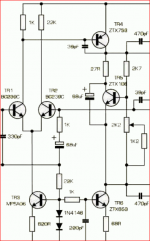
The NAP250 schematic snip below, shows the front end with typical resistor values used from early days until well after 2000 in SMT legacy models. I suggest those or similar value resistors came from the app. notes JV would have worked from. And yes, H2 takes quite a hit when you balance the LTP for minimum distortion. What else would anyone be attempting?
Attachments
Last edited:
I suggest those or similar value resistors came from the app. notes JV would have worked from. And yes, H2 takes quite a hit when you balance the LTP for minimum distortion. What else would anyone be attempting?
The resistor has specific function. JV didn't just copy this from any app note as the value really depends on the schematic. Bigun is correct that this affects hf compensation and how it works can be seen in spice. If i'm not mistaken there is another Naim amplifier that uses different value (but the purpose is exactly similar). If this trick cannot be used, there is another trick that is also used in another Naim amplifier, i.e. using LTP emitter degeneration resistors.
johnego, I was actually replying there to the topic of the previous 2 posts, i.e. the unequal LTP tail resistors of typically 1K2 and 22K in NAP models. If we read old handbooks of audio circuit designs published by semiconductor manufacturers (application notes are published now), we often see patterns of similar topologies and component values applied to several designs and variations, according to the engineering of the day. When these appear in products that follow, the influence is more obvious.
The small value resistor you are referring to is a different matter. To say it has an affect on compensation, I think means thermal compensation of the output stage bias. The temperature coefficient or rate of change of bias per degree change of temperature, is controlled by the value of this resistor and to some extent, by its own bias dividing resistors. Generally, EF output stages need large values of 100-200R and CFP small, maybe 20-40R. QC stages might appear to need something in between but if coupling is via the air and somewhat remote, the coefficient may need to be made greater due to heat loss.
There would be some affect on frequency compensation by the capacitance of the Vbe multiplier circuit but I think any such "Cce" of the transistor might be minuscule and utterly dwarfed by the 47uF capacitor in parallel.
The resistor has specific function. JV didn't just copy this from any app note as the value really depends on the schematic. Bigun is correct that this affects hf compensation and how it works can be seen in spice. If i'm not mistaken there is another Naim amplifier that uses different value (but the purpose is exactly similar). If this trick cannot be used, there is another trick that is also used in another Naim amplifier, i.e. using LTP emitter degeneration resistors.
The input LTP is a pairing of common emitter amplifiers, and the Vas is a single stage example. The datasheets for BC23X types and ZTX 752/753 show a significant difference in the Collector to Base capacitance.
A common emitter amplifier is an inverting stage and such capacitance will be amplified by the gain of the particular stage. The consequences of this are better described in the paper at eCircuitCenter
In considering the impact of the 22k resistor there is a further complication in that the Collector to Base capacitance depends on the area of the junction. That also depends inversely on the voltage applied at the collector which will so involve the junction area.
Thus considered Collector to Base capacitance is inversely proportionate to the square root of the voltage applied at the collector.
Including the 22k resistor in the feedback half of the LTP will reduce the collector voltage and increase the collector to base capacitance.
Also if the capacitance is high the width of the collector expands and that of the base narrows and the gain of the transistor is reduced in proportion and more drive has to be applied to the base to get the same gain level without the collector load.
Judicious use of this could be made without getting deeply into the realm of Early Effect.
There are also loading effects and low pass frequency effects to consider for all three transistors.
The LTP structure may look unbalanced but there are other ways to look at this.
The "tail" of the long-tailed pair is the single connection to the emitters, typically via a current source.johnego, I was actually replying there to the topic of the previous 2 posts, i.e. the unequal LTP tail resistors of typically 1K2 and 22K in NAP models.
Member
Joined 2009
Paid Member
Thanks Gareth,
I can see some of the mechanisms. As Mjona suggests, it could be an Early effect, but more likely to do with the compensation. Anything which permits a smaller Cdom generally sounds better, and it would likely increase asymmetric distortion, viz H2. We know Vereker liked H2, but his customers like the 'sound'.
Given your pelvic analogy, perhaps the stage current flows down the spine, as it should??
Hugh
You're all right, of course. 'don't know why I wrote that instead of emitter resistors but it was in haste and without referring to anything which was bad to begin with.we have the long tail, the other bits we were chatting about are called legs. perhaps the transistors should be called the pelvis.
Thanks Gareth,
Given your pelvic analogy, perhaps the stage current flows down the spine, as it should??
Hugh
On music signal more of a tingle perhaps?
OK, I'll get it right eventually - collector or collectors leg resistors? sticks with wires? them things between the LTP collectors and rail? No description at all might be safest.... emitter resistors....?

johnego, I was actually replying there to the topic of the previous 2 posts, i.e. the unequal LTP tail resistors of typically 1K2 and 22K in NAP models.
If we look at JV's amps (specifically with ltp), we can see that he has consistent 'goal'. He didn't try to balance the current, didn't try to lower common mode effect, didn't try to zero the output DC (some even criticized why he didn't tie the ltp transistors together), didn't even to balance Vce. And personally i don't think that he utilized the ltp to get a good H2 like many have predicted, even if he was fond of H2.
- Status
- This old topic is closed. If you want to reopen this topic, contact a moderator using the "Report Post" button.
- Home
- Amplifiers
- Solid State
- TGM10 - based on NAIM by Julian Vereker