Member
Joined 2009
Paid Member
You need some circuit, that rapidly (in less than 10ms) switches MOSFET on when voltage cross over ~6V, and turn off when falls below ~5V. Shmitt trigger is one of possible solutions.
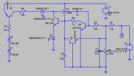
OK, I have simulated a speed-up option on my circuit. The simple addition of a capacitor and some different values for existing parts. There is a tradeoff with the slow-turn-on time, to avoid hearing power-on noises but it looks feasible to improve the turn-off time quite a lot. I think it can achieve 3ms to 5ms.
This capacitor is a kind of Schmitt trigger, i.e. positive feedback.
Attachments
Member
Joined 2009
Paid Member
That's not the Naim sound IMO... Great recordings are slightly subdued and poor recordings are slightly enhanced - the end result is very appealing for long term listening.
'MSG' - that's an interesting description for the sound, there is some enhancement there but MSG tends to taste quite 'fake' to me, some kind of aftertaste, whereas this amp sounds vivid and 'real' on good recordings. Nevertheless, we both perceive some enhancement.
But the overall behaviour is the opposite of what you describe (you say great recordings subdued and poor enhanced but I find great recordings are great and poor are trashed) so maybe I don't have the authentic Naim sound.
Last edited:
Member
Joined 2009
Paid Member
'Thought I'd post this 1991 review of NAP140/NAC62 for some credible numbers and comments on the original combination back then. NAC62 incidentally, is much the same as NAC42 but has more inputs and tape facilities which were still popular at the time. Note the addition of a HICAP power supply is implied for the review and there are 6 pages of it, which isn't all that obvious on a quick scan of the content.
Naim NAC 62 preamplifier & NAP 140 power amplifier | Stereophile.com
Naim NAC 62 preamplifier & NAP 140 power amplifier | Stereophile.com
Member
Joined 2009
Paid Member
Intersting review - I have to agree with many elements of that description. Those that resonate the most with my experience with the TGM10 are:
Treble gives a completely natural rendering of cymbals - spot on!
Remarkably lifelike, presence of the instrument between the two speakers - yes!
Recessed mids - well, yes but just a little, I thought it was the difference between my usual speaker and the PMCs but the mids are less meaty
Voices existing in the room were not subtle - yes, very much so!
Startlingly convincing illusion of the guitar before me - yes again!
Lush bloom around instruments - yes, part of my 'seeing' it as vivid
each instrument being a distinct and independent component...was extraordinary - yes, Exactly!
Well, I found that review really nailed 90% of my feeling about this amplifier. The 10% differences? Well, the sounstage was not deep for me, but still very 3d. The treble was not smooth, it was vibrant. ( the irritability I can get on bad recordings is in the presence région, not the treble, lower treble perhaps and is related to my having some self diagnosed hyperacusis and v mild tinitus).
I read the review 3 times and find it uncanny in its accuracy. Before today I would dismiss that kind of review as gush and guff. I will have to think twice in the future.
Last edited:
90% agreement eh? That's amazing in itself since you may only have the one comparable device in your replay system. Anyway, I think Stereophile is one of the few publications where communication and integrity still matter. It seems many other professional reviewers now get by just as cool wordsmiths, pressing peoples' buttons to raise the drool factor but not offering much in the way of coherent analysis.
Have you tried bypassing the FETs to see if that makes a difference?
There are other suspects, of course.
Vivid, energetic sound does not require irritation.
I built the FET idea for another application. It measured very well. As far as I can see if Rds is low enough the current flow through the drain source junction as if a resistor. Can't help thinking it's not the best idea.
ESP - MOSFET Solid State Relays
thanks for confirming the FETs are part of the SS relay.Andrew, The FETs are there only to isolate the speaker during power-up and power-down and with the hope of mitigating risk of damage should the amplifier put out dc onto the speaker output. Bypassing the signal path through the FETs (this was the suggestion) wouldn't stop the amplifier from working.
Intersting review - I have to agree with many elements of that description. Those that resonate the most with my experience with the TGM10 are:
Intersting review - I have to agree with many elements of that description. Those that resonate the most with my experience with my Naim-like bits are:
"...exchanging the 140 for the VTLs, replacing the 62 with the SP-11) led me to conclude that all the Naim circuits share a common character—lightweight balance, recessed mids, smooth treble—that is compounded by each stage through which the signal passes."
Read more at Naim NAC 62 preamplifier & NAP 140 power amplifier Page 2 | Stereophile.com
Like I said earlier - this homogenises the sound.
I guess the human mind is rather good at reading what we want to read
")
Member
Joined 2009
Paid Member
ha, perhaps they're like the Horoscopes in the Daily MailI guess the human mind is rather good at reading what we want to read


I refered to JLH. This is the version I think remarkable as a design. The capacitor coupling was JLH's choice as his amplifier of about 5 years before was very like all the designs of the time including Naim with LTP.
I may well have put something in the wrong way. Original included ( Hi Fi News Dec 1980 ). I find this way easier to follow.
Note how the input and VAS are much more like his JLH class A amp in terms of current. The really nice thing is very high grade transistors control the MOS FET's . No need for drivers in the usual sense. Set up is 47 mV through the 0R47 drain resistors. If not looking you might think this is a source follower Fetlington type device. It is not, it's a complimentary feed back pair. The distortion should be nearly zero for the output stage before loop feedback as compared with 0.8% if a source follower. The Cdom is shifted to VAS collector and input emitter. JLH says it will work without it. 47 pF sounded and measured ideal. Mostly reactive loads improve with it in place. Measured distortion slightly less without and ears prefered with.
Last edited:
I refered to JLH. This is the version I think remarkable as a design. The capacitor coupling was JLH's choice as his amplifier of about 5 years before was very like all the designs of the time including Naim with LTP.
I may well have put something in the wrong way. Original included ( Hi Fi News Dec 1980 ). I find this way easier to follow.
Note how the input and VAS are much more like his JLH class A amp in terms of current. The really nice thing is very high grade transistors control the MOS FET's . No need for drivers in the usual sense. Set up is 47 mV through the 0R47 drain resistors. If not looking you might think this is a source follower Fetlington type device. It is not, it's a complimentary feed back pair. The distortion should be nearly zero for the output stage before loop feedback as compared with 0.8% if a source follower. The Cdom is shifted to VAS collector and input emitter. JLH says it will work without it. 47 pF sounded and measured ideal. Mostly reactive loads improve with it in place. Measured distortion slightly less without and ears prefered with.
I have the article, circuit board layout and a recent simulation of the direct-coupled version mentioned by JLH. I am reluctant to get off topic by posting here but am happy to provide these to anyone who is interested.
What I wanted to show is at the same time this was the amplifier that beat them all. JLH made it look as it simplicity and cheap build were it's only virtues. Unlike Vereker he wasn't driven to prove it best of type.
It's a neat trick to replace a transistor + very slow Darlington triple with this hybrid double ( the earlier version with Darlington ). For fun I built this amplifier type without the transistor before the FET, If you like a FET VAS driving the speaker with FET CCS at 8 watts. It had a weird sound as the output impedance was way too high. It sort of worked for electric guitar and even went loud, almost like a pentode valve. Even though the JLH hybrid transistor has a 220R resistor stopping it giving current to the load the negative feedback ( which is massive ) just like the Naim bottom NPN will have a very low output impedance. Note also he uses 330R and 1K2 stoppers to the output doubles to match the sides ( neat ). Thus a transistor only usually suited to gain stages can turn a drain output FET into a pile driver rather than a chocolate screwdriver. How wonderful is that?
BTW. JLH likes the protection the output capacitor gives. Out of all the things that you could own this capacitor is hard to fault soundwise ( forget what you have read, even very cheap caps are not a disaster even on measurements ), I bet your CD player can't make that claim even if it cost a fortune ( error correction mostly and final integration, old 1990's Crystal 20 bit DAC my favourite, a JLH sound when a DAC, good HF detail ).
I am convinced this and the Hitachi amplifier using these MOSFET's have been forced out of the picture as if a political thing. JLH showed how to make them work, others said " don't bother ". It seems all to hinge on ultimate power into 3 ohms. Music mostly is mid band where seldom do we need 5 watts. In the mid band this amp excells. I suspect this circuit would drive double FET's if asked. It might just drive cheaper FET's like IRF540/9540 if the bias is stable. Ron is 0R2 ( 0.07 N type ) which might be OK.
As you say this thread looks at Naim. This is " what if ". Notice the same output solution as the Naim using OR22. Distortion balance will be similar and preferable when JLH. Unlike Self JLH used his ears to complete the job. He reasoned stability into reactive loads prime and lost a bit of HF spec as a trade off. As the amp worked without his Cdom he could do it by ear. That is an interesting idea as the reactive load must hinder feedback or even cause danger. As there are doubts we can hear distortion when the harmonic in doubt is >30 kHz, it could be that an easy to drive Cdom that kills the amplifier gain early will sound better. It will look less good ( still very good ) into a resistive load.

I got my FET arrows wrong. As far as I know the 47 pF compensation is drawn correctly. The phases look wrong to be a Cdom and JLH doesn't say it is. Could be there is just enough phase shift to work and is only for reactive loads. Not bad if so. Refer to 1054 for JLH dia. Anyone see how it works?
I have seen him use a current source like this before. I could imaging the more conventional one often seen would be as good. Maybe this one tracks the output?
It looks to me analogous to the Miller cap being connected to the emitters of the LTP rather than to the VAS transistor base. JLH has only half an LTP. I can see how it works but I'm not sure what the benefit is of sending the Miller feedback through an extra transistor...that will reduce stability. A benefit may be that you can get away with a mediocre Miller capacitor.
I'm not sure what it is about the JLH design that you like so much...I don't see much refinement about it compared with the NAP but I am happy to be enlightened.
I'm not sure what it is about the JLH design that you like so much...I don't see much refinement about it compared with the NAP but I am happy to be enlightened.
Last edited:
Member
Joined 2009
Paid Member
That 47pF from the VAS to the feedback node is simply local phase lead compensation. In the NAP it's across the feedback series resistor (here shown as 22k). There is no explicit Cdom in the JLH design. Part of the reason is that the singleton input has less need for it than the LTP - as far as I know you can't avoid it when using an LTP. What I did notice about this JLH design is that it appears to operate the CFP outputs without any local Cdom on the driver device.
Member
Joined 2009
Paid Member
- Status
- This old topic is closed. If you want to reopen this topic, contact a moderator using the "Report Post" button.
- Home
- Amplifiers
- Solid State
- TGM10 - based on NAIM by Julian Vereker