And I don't understand these phase networks
I will not tell the exact answer but this statement should lead you to the answer if you need to investigate further:
Why do you think there is Baxandall diode in this topology? Because this is a very asymmetrical push pull amplifier topology.
The idea of the phase networks in the forward path is one Julian Vereker saw in another amplifier - he did mention the brand, which I think was of American origin. The maker whom I have forgotten was not a major brand.
With a Darlington pair in the upper output half and a Complementary pair opposite there are differences in phase which will be summed due to a common negative feedback path and IMD would result from that process.
Without the Baxandall diode in the lower half there is only one diode forward junction in the output pairing. There are two in the upper half. The idea of the addition diode in the lower complementary pair was widely adopted after Baxandall's letter was published in Wireless World issue of September 1969, pp 416-417.
The Darlington has a bias voltage of about 1.2 vdc. The lower complimentary feedback pair about 0.7 vdc. The diode makes it 1.2+1.3 . The argument in the day was npn was faster.Julian is quoted by Douglas Self as saying npn and pnp matched pairs are as identical as men and women of the same weight and height. Self thought it still slightly valid. Some amps use twin complimentary feedback pairs. The double complimentary feedback pairs have remarkably low distortion. Without any loop feedback I measured 0.05% thd up to 60 kHz as an op amp buffer ( opa604 ).
The point being filtering the bottom end of a speaker should give lower distortion.
Why should we love patches when a good speaker can be designed without it? A good woofer should not produce mechanical sound and the enclosure should be designed to take care of the Fs. And a good amp should provide a proper LF (opposite of putting HPF).
Member
Joined 2009
Paid Member
With a Darlington pair in the upper output half and a Complementary pair opposite there are differences in phase which will be summed due to a common negative feedback path and IMD would result from that process.
so this could be a valid approach wherever the phase shift of upper and lower elements of a totem pole output are mismatched. Given that a bog standard EF output stage has different junction capacitances between n and p type such phase networks could be of value in this case too ?
Why should we love patches when a good speaker can be designed without it? A good woofer should not produce mechanical sound and the enclosure should be designed to take care of the Fs. And a good amp should provide a proper LF (opposite of putting HPF).
It's useful to know.it can be an option. I use a 15 inch and 12 inch together. It works. I have a 20 Hz filter first order to the 12 inch. 15 inch 5 Hz and 20 dB boost 20 Hz It's a baffle type.
so this could be a valid approach wherever the phase shift of upper and lower elements of a totem pole output are mismatched. Given that a bog standard EF output stage has different junction capacitances between n and p type such phase networks could be of value in this case too ?
Yes you can but as i said you don't need to. Most of the problems can be solved without it and the network itself has compromises. It is not a coincident that Naim provides their own cable if i'm not mistaken.
so this could be a valid approach wherever the phase shift of upper and lower elements of a totem pole output are mismatched. Given that a bog standard EF output stage has different junction capacitances between n and p type such phase networks could be of value in this case too ?
We have better NPN and PNP complements these days in comparison to those available in the 1970's. With an EF2 like Self's Blameless or an EF3 where the driver transistor emitters are cross coupled I would say it is not worth the effort.
The dominant pole is around the Vas transistor. If the harmonics are to descend monotonically the cancellation has to be arranged so the feedback ones don't clash with the forward ones.
In a conventional circuit that I tested some years ago increasing the dominant pole compensation favoured odd order harmonics. This is somewhat analogous to timing the changes on a dodgy sychromesh gear box in a car. There are other elements in the Naim circuit to investigate in the time domain - this can be done by looking at a suimulation of sine wave peaks for the LTP currents at 20kHz to see where these fit along the time axis. I looked at the currents through the collector resistors which is a bit messy due to switching effects and shows a disparity in levels between these current levels.
In a conventional circuit that I tested some years ago increasing the dominant pole compensation favoured odd order harmonics. This is somewhat analogous to timing the changes on a dodgy sychromesh gear box in a car. There are other elements in the Naim circuit to investigate in the time domain - this can be done by looking at a suimulation of sine wave peaks for the LTP currents at 20kHz to see where these fit along the time axis. I looked at the currents through the collector resistors which is a bit messy due to switching effects and shows a disparity in levels between these current levels.
Last edited:
Years ago when I joined this thread someone had bought a transformer that gave 50vdc and was worried. I suggested the raw DC as usual for a nap140 be fed to the output pairs and +/- 40vdc to the rest of the amplifier. I argued this might beat the nap250. Funny how no one took this up. There is more to that idea than is obvious. As long as the output pairs are more than ripple voltage higher than the vas plus 3v for safety the output not only is a current amplifier it also works as a voltage regulator in it's action. This means no using music to mask ripple noise. Also no ripple to the vas.
BTW, the mysterious 22k LTP resistor is also part of this scheme.
You could say apart from DC servo action it almost isn't therre.
As for vas having monotonic harmonics. It would if perfect. The output at the brake frequency is approximately a third order effect. This means uncorrected high order distortion.Two pole vas correction could help. Self shows typically that the compensation is if 22pf becomes 220pf + 22pf the + point 2k2 to either ground or voltage rail. This idea from op amps. Another idea is to the output. Stability might be n issue if the output.
You could say apart from DC servo action it almost isn't therre.
That may be so at zero hertz however my point about Miller capacitance does seem to not registered that much in general thinking.
This depends inversely on the sq.root of voltage seen at the collectors in common emitter amplifiers and this will change in dynamic situations.
The 22k resistor reduces the voltage at the collector of the inverting transistor so the width of diffusion capacitance in this is increased and figures prominently.
With the Vas there is an external capacitor to swamp the non-linear capacitance in the diffusion.
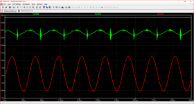
In the attached 20k simulation .raw image the line at the top is the collector voltage of the input transistor, the second is that of the feedback transistor and the bottom one the Vas.
Attachments
but I can't identify anything about the sound of my TGM8 that should be improved so I've called it a day
That's interesting. My vocabulary for quality measures is so wide that i never had one amp that couldn't be improved. Many of these quality aspects can be easily associated with Physics/numbers but a few more is rather a mystery or i'm not sure 100% of the Physics it is correlated with. If its correlation is easily determined the improvement is easy because i know which direction to go. But if not...
As for CFP amps, look at the level of the crossover distortion or cross conduction in your amp. Do you have very good intelligibility? I would think not. I have tried to make such amp to sound good with minimal bias (such as 30mA like in Naim?) but i could get away with only 70mA minimum.
I predict that your amp's ULGF is slightly below 2MHz? I will describe one quality measure that will be hard to achieve:
Do you like singing? If you like singing, there are amplifiers that will make you sing along (if you like the song). There are other amplifiers that do not invite you to sing along and worse, even if you try to sing along, the pitch or whatever it is called would prevent you to do it unless may be you use head voice.
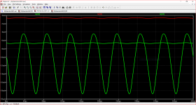
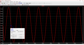
I have adjusted the output standing current to clean out the spikes in my previous simulation as shown attached.
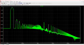
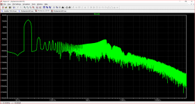
The FFT result corresponding to this is also attached.
The first of these two simulations is too distant to see what contributes to the FFT result. The 22k collector resistor and the step network in parallel with the feedback resistor add fine tuning.
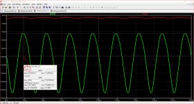
For a closer view I simulated the emitter currents for Q2 (feedback)and Q1 (input) separately to see how closely the respective current peaks aligned with each other in the time domain.
I looked at Q2 first and there is a peak in the current at 36.8us - see the cursor and result box for detail.
I then looked at Q1 at 36.8uS and set the cursor at that point - more on this in my final summary.
Further the variation in current over the operating range for Q2 was 14.4 m.A. while that for Q1 was 146 u.A. so of the pairing Q2 is more dominant - thrusting in opposition to Q1.
Over a 146 u.A. current operating range Q1 will be working over a smaller distance on the gain plot line - the flatness between two points giving a more linear output.
Anyway, at 36.8 uS the cursor for Q1 lays nowhere near any peak in Q2.
The internal diffusion capacitance in Q2 will also vary with the a.c.voltage applied at the output and the 22k resistor lowers the collector voltage for starters.
The combination of those two factors prompts thinking about a timed combing effect filtering the harmonic structure of the feedback signal and the amplifier output.
The FFT result corresponding to this is also attached.
The first of these two simulations is too distant to see what contributes to the FFT result. The 22k collector resistor and the step network in parallel with the feedback resistor add fine tuning.
For a closer view I simulated the emitter currents for Q2 (feedback)and Q1 (input) separately to see how closely the respective current peaks aligned with each other in the time domain.
I looked at Q2 first and there is a peak in the current at 36.8us - see the cursor and result box for detail.
I then looked at Q1 at 36.8uS and set the cursor at that point - more on this in my final summary.
Further the variation in current over the operating range for Q2 was 14.4 m.A. while that for Q1 was 146 u.A. so of the pairing Q2 is more dominant - thrusting in opposition to Q1.
Over a 146 u.A. current operating range Q1 will be working over a smaller distance on the gain plot line - the flatness between two points giving a more linear output.
Anyway, at 36.8 uS the cursor for Q1 lays nowhere near any peak in Q2.
The internal diffusion capacitance in Q2 will also vary with the a.c.voltage applied at the output and the 22k resistor lowers the collector voltage for starters.
The combination of those two factors prompts thinking about a timed combing effect filtering the harmonic structure of the feedback signal and the amplifier output.
Attachments
Member
Joined 2009
Paid Member
I think at this level of detail you have to double check the simulation parameters or the FFT can get difficult to work with. This includes ensuring the FFT window stops and starts on whole waveforms with enough points and after enough time steps etc. This is far from my area of expertise but there’s been some discussions about this and looking at you plots reminded me of the topic.
Member
Joined 2009
Paid Member
Well, I hope eventually you too find your own ‘TGM8’, that special amp which your ears tells you should not be improved.My vocabulary for quality measures is so wide that i never had one amp that couldn't be improved.
In the meantime we are learning about this Naim amp to see where it’s end point should be.
I think at this level of detail you have to double check the simulation parameters or the FFT can get difficult to work with. This includes ensuring the FFT window stops and starts on whole waveforms with enough points and after enough time steps etc. This is far from my area of expertise but there’s been some discussions about this and looking at you plots reminded me of the topic.
I re-ran the test with a start time of 200uS as per Bob Cordell's tutorials for 20kHz sine wave and THD. . The simulation I used was set up for square wave testing. In adapting this for sine wave I omitted the THD .commands - so much for that short-cut, I should have seen better.
The amended FFT is attached.
Attachments
- Status
- This old topic is closed. If you want to reopen this topic, contact a moderator using the "Report Post" button.
- Home
- Amplifiers
- Solid State
- TGM10 - based on NAIM by Julian Vereker