Gareth, I noticed your discussion over at Greg's site on grounding. FYI, I used the scheme recommended by Greg with the separate disconnecting networks from each board straight to a common chassis point, and it is absolutely, totally, noise free without me putting any special care into lead dressing etc. I noted you have other reasons for your questions on this (regarding the interation with PCB parts etc) and you're far cleverer than me on this, but just wanted to relate my experience on this issue.
Member
Joined 2009
Paid Member
I just look at the circuit and apply what engineering knowledge I have. At the end of the day Greg reports, as you do, the success he has with the earthing scheme he's used and you can't argue with that. For me it's different, I'm only here to question and learn stuff - that's why I didn't build the GB150 as designed, I changed it 
the Main Audio Ground to Chassis connection is for Safety only.Gareth, I noticed your discussion over at Greg's site on grounding. FYI, I used the scheme recommended by Greg with the separate disconnecting networks from each board straight to a common chassis point, and it is absolutely, totally, noise free without me putting any special care into lead dressing etc. I noted you have other reasons for your questions on this (regarding the interation with PCB parts etc) and you're far cleverer than me on this, but just wanted to relate my experience on this issue.
In normal use this link should pass zero to miniscule current.
The Disconnecting Network should as a result of passing this tiny current have a tiny voltage across it.
Measure the voltages and report.
These voltages to chassis should have no impact on the sound quality of the amplifier channels. Similarly these DN links should not affect, nor be affected by, cable dressing.
Cable dressing will have an effect where loop areas are non zero. i.e. the Flow and Return pairs will be impervious to interference fields where the loop areas are zero. Where loop areas are non zero, then interference fields may have an audible impact and here dressing may have a benefit. But that is the wrong cure. Zero loop area in the emitters and zero loop area in the receivers are the solutions, not dressing.
Member
Joined 2009
Paid Member
I tend to focus on keeping outgoing current and return current in close parallel wires - in other words, small loop area.
Here's a few comments on the choice of np0 capacitors: http://www.diyaudio.com/forums/parts/77299-ceramic-capacitors.html
check out the plot in post 7.
and
http://www.diyaudio.com/forums/parts/168423-c0g-np0-coupling-caps.html
Here's a few comments on the choice of np0 capacitors: http://www.diyaudio.com/forums/parts/77299-ceramic-capacitors.html
check out the plot in post 7.
and
http://www.diyaudio.com/forums/parts/168423-c0g-np0-coupling-caps.html
the Main Audio Ground to Chassis connection is for Safety only.
In normal use this link should pass zero to miniscule current.
The Disconnecting Network should as a result of passing this tiny current have a tiny voltage across it.
Measure the voltages and report.
These voltages to chassis should have no impact on the sound quality of the amplifier channels. Similarly these DN links should not affect, nor be affected by, cable dressing.
Cable dressing will have an effect where loop areas are non zero. i.e. the Flow and Return pairs will be impervious to interference fields where the loop areas are zero. Where loop areas are non zero, then interference fields may have an audible impact and here dressing may have a benefit. But that is the wrong cure. Zero loop area in the emitters and zero loop area in the receivers are the solutions, not dressing.
Andrew, you have to have seen the other discussion referred to, to understand why I made the statements I did.
I don't know for all you seem convinced that I should be aware.
My comments are saying that in my opinion cable dressing should be relatively unimportant. Your comments seem to be saying something similar.
Get rid of the transmitters of interference. Get rid of the receivers of interference.
Then cable dressing becomes much less important.
Then both amplifiers in the common Chassis will NOT rely on Screening effect of the Chassis. The only job left for the MAG to Chassis connection is purely Safety. There is no audio advantage in connecting MAG to Chassis.
If Chassis to circuit connections are required for audio reasons then usually these will be made at the cable entry point not at the MAG.
Sure.
FYI, Gareth asked Greg about his recommended grounding solutions - both safety and audio ground - because he had some ideas about alternatives for grounding. Greg explained his point of view why he recommends what he does, including the disconnecting networks and also with respect to the audio ground.
Elsewhere on his forum, Greg made the point that attention to cable dressing within the chassis gives the last bit of finesse to the 'blackness' of silences and the perception of 'air'.
I merely related my observation that even without particular attention to cable routing, my implementation is dead silent using the recommended grounding. I only mentioned the disconnecting networks because it was a notable part of their discussion.
Cheers
Stu
I just look at the circuit and apply what engineering knowledge I have. At the end of the day Greg reports, as you do, the success he has with the earthing scheme he's used and you can't argue with that. For me it's different, I'm only here to question and learn stuff - that's why I didn't build the GB150 as designed, I changed it
Absolutely. You're miles ahead of me there! I get great entertainment reading threads like this for that reason. Same with Mr T's comments...very educational, in line with his day job!
Member
Joined 2009
Paid Member
Well I have been distracted building a pair of speakers for a friend, a rather nice pair of Pencil's using the Alpair 10.3. I like this driver.
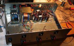
Anyhow, slowly getting back to the amplifier as day job permits. I'm recycling an old Fisher stereo chassis, with transplanted power trafo, heatsink and new rear panel. I've had to move around some of the chasis pieces so it's a bit of a mongrel now.
But the soft start circuit, power trafo, bridge rectifier and filter caps are all installed. The main ground return and power rail wiring is in place. More bits to add yet - maybe at the weekend.
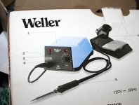
p.s. treated myself to a new soldering iron. It's my very first soldering station (rather than the iron from Home Depot you can see at the edge of the photo of the bench top), with a cleaning sponge and a spring thing to rest the iron in. Never had any of this before and I haven't yet fired it up (poor choice of words maybe) - saving it for when I get to put together the last pair of pcb modules.
Anyhow, slowly getting back to the amplifier as day job permits. I'm recycling an old Fisher stereo chassis, with transplanted power trafo, heatsink and new rear panel. I've had to move around some of the chasis pieces so it's a bit of a mongrel now.
But the soft start circuit, power trafo, bridge rectifier and filter caps are all installed. The main ground return and power rail wiring is in place. More bits to add yet - maybe at the weekend.
p.s. treated myself to a new soldering iron. It's my very first soldering station (rather than the iron from Home Depot you can see at the edge of the photo of the bench top), with a cleaning sponge and a spring thing to rest the iron in. Never had any of this before and I haven't yet fired it up (poor choice of words maybe) - saving it for when I get to put together the last pair of pcb modules.
Attachments
Last edited:
Member
Joined 2009
Paid Member
It's me that needs the belly band
Actually it was there when I took it out of a Pioneer HT receiver. I was quite impressed to see that it had one. I like them - I fitted them to the trafo's in my tube amplifier.
I take your point about the gnd connection, that's something I may tidy up before I put the lid on. Hopefully soon. Right now I'm about to hand off a pair of speakers I built, my friend is coming around today to check them out and decide what else is needed.
Member
Joined 2009
Paid Member
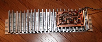
Because I am not going to install the input capacitors there is always the danger that a bad source will result in dc at the output. So I am installing a dc protection circuit (conveniently mounted on the backside of the heatsink). This design is recycled from an earlier project and uses very low Rds-on MOSFETs as solid state relays and a circuit to turn-off the output if dc is detected. There are catch diodes to prevent damaging voltage spikes from back emf when the speakers are disconnected. No delayed turn-on included - will see if this is needed or not during testing.
Attachments
Member
Joined 2009
Paid Member
The belly strap runs underneath - it has to run around the outside of the E-core or else it would represent a shorted turn for the main flux and quickly overheat - clearly Pioneer would not make that mistake. However, there's a mounting flange under the trafo between the belly strap and the chasis. The electrical connection to the chasis looks like it should be good but I haven't checked it. I suspect it makes a reasonable contact with the chasis, which I would prefer to leaving it floating. The purpose of the strap is that it acts like a shorted turn for stray flux, the leakage inductance. Hence copper for it's good conductivity - the leakage flux generates a current in the belly strap which in turn generates an opposite field to the stray flux and cancels most of it out. Rather than rely on it to keep stray fields out of the amplifier I have positioned the heatsink between the power trafo and the amplifier pcb so that the amplifier is kept further away from the trafo - stray fields decay rapidly with distance. I have also designed the amplifier pcb traces with minimal loop area to reduce pick up any stray fields and the input wiring is short and also with minimal loop area.
Last edited:
Yes. From the photo it just looks like a flat steel cover on top but I wasn't sure if it was earthed as it could be isolated from the laminated core. I have a large transformer of similar construction I salvaged from an amp...that is, with the copper band. Waiting for a suitable project in which to use it. Might have a look again now yours has piqued my interest, as I'm thinking of building a second GB to biamp my speakers.
Member
Joined 2009
Paid Member
Well I've got things hooked up enough that I can power up in the chasis. Being rather eager and confident that it was working fine at 20V rails I plugged it in with fuses removed. Poof - little rising twirl of smoke from one of the 100R resistors I had mounted in parallel with the fuse holders. It isn't just a case that these resistors are under-rated but there was a lot of volts across it, instant frying. I removed the debris and removed the remaining 100R resistor under the other fuse holder. I won't be using them again, too fragile.
So I used a sturdier resistor connected to the empty fuse holder by crocodile clips (the other fuse was not removed). Still too much current and it was not adjustable. To cut a long story short, since last testing the amplifier out one of the power FETs appears to have developed a cold solder joint - a fragile joint as it turned out since it almost fell off the board. By desoldering and re-soldering it I was able to get things working again. Rather embarasing - I don't remember having a cold solder joint before. So I punished myself by accidentally picking up the iron by the hot end! ... hmmmmm
The amplifier is sitting on the workbench with about 60mA idle current per FET, no load and no input. Both fuses installed and measuring the bias current across the resistor in the power supply rail and across one of the FET source resistors. I am noticing that the bias adjustment gets very touchy when I try to go higher than 60mA per FET even though it was perfectly fine when being used with 20V rails. This is not a thermal issue, over the past 10 minutes the heatsink has warmed up considerably but current draw is rock solid. I suspect an oscillation so it's time to get out the scope.
Further work needed...
Last edited:
- Home
- Amplifiers
- Solid State
- TGM7 - an amplifier based on Greg Ball SKA