Hi all!
What is the best tube/valve for preamp or line-stage i.e. that gives the best sound?
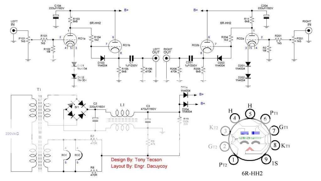
Is this a good schematics?
Why are the (1/2-6DJ8 + 1/2-6DJ8) tube/valve in this configuration (schematics) connected in parallel?
(1/2-6DJ8) + (1/2-6DJ8) in paralle.
It can be replaced 6DJ8(6922) with PCC88 and who changes that are needed in the schematics?
thank you!
What is the best tube/valve for preamp or line-stage i.e. that gives the best sound?
Is this a good schematics?
Why are the (1/2-6DJ8 + 1/2-6DJ8) tube/valve in this configuration (schematics) connected in parallel?
(1/2-6DJ8) + (1/2-6DJ8) in paralle.
It can be replaced 6DJ8(6922) with PCC88 and who changes that are needed in the schematics?
thank you!
Attachments

Last edited:
define "best".....
Hi Tony!
Give an opinion on this schematic or a suggestion for pain tube/valve preamplifier, line-stage or buffer.
thank you!
That was going to be my question too!
The circuit looks like a good example of how not to do a line stage. For example, choose a valve with a low output impedance then put it into a circuit which increases it dramatically.
The circuit looks like a good example of how not to do a line stage. For example, choose a valve with a low output impedance then put it into a circuit which increases it dramatically.
Hi Tony!
Give an opinion on this schematic or a suggestion for pain tube/valve preamplifier, line-stage or buffer.
thank you!
what is best for me may not be best for you, we are not the same person...😀
a Broskie CCDA works fine for me, i can hear no difference between it and the Aikido, both Broskie's....
the scheme shown below has a B+ of about 130volts, you can replace the diodes in the cathode of the input tube with 82 ohm resistors...
tube can be ECC88, 6922, 6dj8, etc...
wow, a working curcuit 😀 looks 'appealing'
why the 1K5 att input pot ?
how can you use such small one ?
why the 1K5 att input pot ?
how can you use such small one ?
What is the purpose of the common-mode choke L1? It appears to be in the wrong place to attenuate rectifier spikes, and it will have little effect on smoothing.
Perhaps he doesn't like the answers he gets, so like a politician keeps asking the same question again and again hoping for a different result. Or maybe he has poor memory?
Thank you!
Tony, thanks for schematics. I have two PCC88 what changes are needed to the schematics, that is, the value of which components to change?
Do potentiometer P101 can be set to output and input to be inserted autenator R1/R2?
Thank you for your cooperation!
Cheers!
what is best for me may not be best for you, we are not the same person...😀
a Broskie CCDA works fine for me, i can hear no difference between it and the Aikido, both Broskie's....
the scheme shown below has a B+ of about 130volts, you can replace the diodes in the cathode of the input tube with 82 ohm resistors...
tube can be ECC88, 6922, 6dj8, etc...
Tony, thanks for schematics. I have two PCC88 what changes are needed to the schematics, that is, the value of which components to change?
Do potentiometer P101 can be set to output and input to be inserted autenator R1/R2?
Thank you for your cooperation!
Cheers!
Last edited:
Member
Joined 2009
Paid Member
don't know, but is it good to have a choke in the grounding line ?
I don't see any problem with it, the signal ground is an artificial reference point for the circuit, you can place it pretty much anywhere you want.
I said:
Your question about the difference in using a PCC88 has been answered already in one of your other threads. The answer is also widely available on the internet. No matter how many times you ask this question you will still receive the same answer from people who know; answers from anyone else can be ignored.
Please do not misquote me, in red or any other colour.DF96 said:Perhaps he doesn't like the answers he gets, so like a politician keeps asking the same question again and again hoping for a different result.
Your question about the difference in using a PCC88 has been answered already in one of your other threads. The answer is also widely available on the internet. No matter how many times you ask this question you will still receive the same answer from people who know; answers from anyone else can be ignored.
No you can't. A CM choke reduces common-mode HF noise, so you need a common-mode HF noise source. Rectifier hash will be mainly differential-mode so it won't stop that. It might help with the small proportion which is common-mode, but caps can do that anyway.Bigun said:I don't see any problem with it, the signal ground is an artificial reference point for the circuit, you can place it pretty much anywhere you want.
A CM choke could reduce rectifier spikes getting coupled into the heater circuit via transformer winding capacitance (thanks to SY for reminding me of that) but to do that you would put the CM choke before the reservoir cap, so the cap stray capacitance to ground does not bypass the choke.
OK
Ok DF96, I get it, the PCC88 heater is powered with 7.6V and current of 300mA, and the ECC88 with 6.3V and current of 285mA.
thank you
I said:
Please do not misquote me, in red or any other colour.
Your question about the difference in using a PCC88 has been answered already in one of your other threads. The answer is also widely available on the internet. No matter how many times you ask this question you will still receive the same answer from people who know; answers from anyone else can be ignored.
Ok DF96, I get it, the PCC88 heater is powered with 7.6V and current of 300mA, and the ECC88 with 6.3V and current of 285mA.
thank you
wow, a working curcuit 😀 looks 'appealing'
why the 1K5 att input pot ?
how can you use such small one ?
i have lots of them....😀
Ok DF96, I get it, the PCC88 heater is powered with 7.6V and current of 300mA, and the ECC88 with 6.3V and current of 285mA.
thank you
the pcc88 will work just fine even at a filament voltage of 6.3.....anyway when i design traffos, i aim for a terminal voltage of 6.9 volts reason being they will sag later when the traffo is loaded....
What is the purpose of the common-mode choke L1? It appears to be in the wrong place to attenuate rectifier spikes, and it will have little effect on smoothing.
agreed on the little effect on smoothing, the filter caps take care of that....
 misquote removed.
Ua=160....180V??
Hi guys!
I'm interested in this line-stage from Tony that the output impedance Zout = a? and how is his gain?
Is anyone have some kind remarks about them?
What can I change for the schematic DC-voltage anod B+(Ua)=160?
Is the output can be set to a logarithmic potentiometer P101=2X22k, and at the input to ask autenat 4k7/22k?
thank you!
Last edited:
- Status
- Not open for further replies.
- Home
- Amplifiers
- Tubes / Valves
- The Best tube/valve sound!?