I will be. Just got the heat sinks. Will post as soon as I get time. I built the F4 beast one channel only but the temp control was unstable so I'm hoping with this biasing arrangement I will have success.
I’ve been reading this thread for a while and really wanted to make a HGF. Then I read the F5m Redux thread and was blown away by @N Brock’s amazing design. So now I have committed myself to a HGF hedge hog.

All of the hard work has been done by @lhquam @N Brock and @Mark Johnson. Hopefully my KiCAD skills are up to it. Plan to design a footprint that will combine a SOT-227 hockey puck and a TO-247 to allow a bigger choice of mosfets if it fits on the PCB (I did something similar with my XA252). I will put a 12V trigger on the external power supply. I recently got myself a WIIM Ultra which is great for managing 200gb of music, Qobuz and internet radio and will look good between two hedgehogs. The ultra has S/PDIF and 12V trigger outputs. For the power socket I found the KPJX-4S—S, it looks like it would work well for this project with the KPPX-4P connectors.

All of the hard work has been done by @lhquam @N Brock and @Mark Johnson. Hopefully my KiCAD skills are up to it. Plan to design a footprint that will combine a SOT-227 hockey puck and a TO-247 to allow a bigger choice of mosfets if it fits on the PCB (I did something similar with my XA252). I will put a 12V trigger on the external power supply. I recently got myself a WIIM Ultra which is great for managing 200gb of music, Qobuz and internet radio and will look good between two hedgehogs. The ultra has S/PDIF and 12V trigger outputs. For the power socket I found the KPJX-4S—S, it looks like it would work well for this project with the KPPX-4P connectors.
for what it's worth, Mouser is showing that nearly 5K of the part FQA36P15 is "On Order".
Kind regards,
Drew
Kind regards,
Drew
COPYING everyone's hard work I came up with this PCB. It has many compromises to keep all the sockets at the rear. TO-247 or SOT-227 mosfets fit. 140mm or 160mm diameter heatsinks could be used, 160mm fans are hard to find but have the same mounting hole positions as 140mm. Not sure what is the best way to get 9V for the fan, used a zener and an LM317. This is a work in progress.
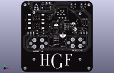
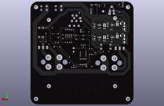
The two blue circles represent 140mm and 160mm heatsinks. If anyone can do a better layout I would probably copy that too.
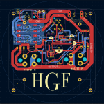
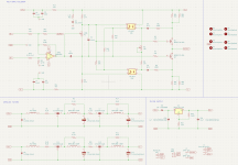
The 9V circuit is simple and can be optimised to the input voltage. Could squeeze a pot in there too and make the fan speed adjustable.


The two blue circles represent 140mm and 160mm heatsinks. If anyone can do a better layout I would probably copy that too.

The 9V circuit is simple and can be optimised to the input voltage. Could squeeze a pot in there too and make the fan speed adjustable.

I just spoke to Mouser, the order was placed on the 9th, so it's going to be a long time. Those are manufactured of course in the ROC and that adds a lot of time to their arrival in the US.for what it's worth, Mouser is showing that nearly 5K of the part FQA36P15 is "On Order".
Kind regards,
Drew
Cheers,
Greg
Hi ElliJ,
Looking at your pcb layout, I see that you have incorporated the AmyAlice power supply filter. I have a suggestion as to the implementation of the Ground.
The power from the external power supply into the filter is assumed to be not so clean, and as the current flows through the filter it becomes cleaner. The output of the amplifier power supply is at the output of the AmyAlice filter, where the power is the cleanest. The best place to connect the amplifier circuit ground, or audio ground, is at the output of the amplifier power supply, which is at the output of the AmyAlice filter.
I also suggest that the external power supply ground be routed with the external power supply V+ and V- to the input of the AmyAlice filter. That keeps the loop area small and also keeps the "dirty" ground away from the clean ground.
Going for the 160mm I see, just had to one up me huh? 
Keep up the good work!

I used a small DC-DC converter.Not sure what is the best way to get 9V for the fan
Keep up the good work!
@N Brock, it’s not the size that matters (I hope). There is only one fan that is suitable I think (Google SF-160 fan). You could put the same fan and heatsink on the F5m Redux with no changes. I don’t have a temp switch, my 9v supply is untested and my layout has lots of compromises so will be happy if it sounds good. I am going for pucks, +-30v supply, skinny standoffs, wafer thin PCB and a slightly different type of heatsink. Fingers crossed for no magic smoke.
I ordered some heatsinks from Aliexpress but they told me there is no stock, but there was when I ordered. I went with D165mm H80mm from digikey £45. Fans were on Aliexpress £19 each.
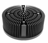
I ordered some heatsinks from Aliexpress but they told me there is no stock, but there was when I ordered. I went with D165mm H80mm from digikey £45. Fans were on Aliexpress £19 each.

PADLED-16580
Thought I would share an update about my discrete front end project for the HGF after a couple months of useage. The novelty / new car smell should be worn off by now. Yes I am fully aware it's just another BA-3 style derivative that's been done to death by now. I obviously haven't invented anything here.. just plugging in the Lego block. One small thing I missed on the schematic at post #691, was a 330pF COG cap in parallel with R2, for the input filter. I just have that installed on the solder source side of the PCB. The boosted / regulated front end supply - this has worked out great. I wondered if I would be able to notice any subjective difference going this route, I believe I do and really like it. The overall sound is "free-er", less restrained... fast and dynamic. Pretend the car you were driving had brakes that were dragging... now released... Dynamics and headroom seem better. Sounds like a slightly more powerful amp. My external supply is a little cumbersome, but not too bad. I had a bad ground loop initially (not surprising), that was fixed by connecting the grounds of the two supplies together with a short fat wire (the boards are stacked), and branching out from there, "T" style. If I was more savvy, skilled, and determined I might see if I could layout a new PCB and integrate an A75 style voltage doubler along with the regulator stuff, to get everything built-in to the amp, as a more elegant and permanent solution. As it is, I'm very pleased at the outcome and enjoy listening to the system very much these days. I feel the performance is at a very high level, well recorded tracks are stunning where you can't help to grin a little with what's being laid out in front of you... Not sure what's in this Holy Grail.. but it's pretty darned good! 

Hi,
please drop LTSpice models for FQA28N15/FQA36P15 if you have,
thank you in advance,
regards
Pawel
please drop LTSpice models for FQA28N15/FQA36P15 if you have,
thank you in advance,
regards
Pawel
Except the IXYS IXTQ36P15P FETs, do not have accurate spice models, but I am working on it.
I have been testing a procedure for accurately computing small-signal FET gm and lambda at a particular operating point. I just acquired a 5-1/2 digit multimeter for accurately measuring the AC voltages required and verifying the behavior of the new measurement circuits. The procedure has been verified and a PCB is ready to order.
I have bench tested the procedure on an IXYS IXTQ36P15P FET and measured gm=4.97 lambda=0.011 with an operating point of 24V and 1.3A. From these values, Kp is computed as 7.53.
I have not had much time to work on my HGF. Had some trouble drilling the heatsink, I kept snapping bits. I have drilled a few heatsinks in the past and not had issues, the metal of these is really soft. Finished tapping one and the SMT on one PCB too. I assembled an amp to see how it will look, not quite as good as @N Brock’s, but not too bad either. Have to lots of uni work at the moment but will try and finish them next weekend.
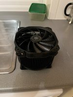
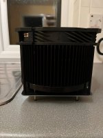
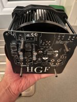


Last edited:
Are you using a drill press? What about aluminum cutting fluid? Both of these will help with drilling and tapping hole.Had some trouble drilling the heatsink, I kept snapping bits. I have drilled a few heatsinks in the past and not had issues, the metal of these is really soft.
I was using a drill press but not cutting fluid. The drills were not getting hot. I even got some Bosch hss bits after breaking a couple. The metal seems softer than normal. I will take your advice and use some cutting fluid next attempt.
Found time to finish drilling the heatsinks and with some oil I had no problems. Thanks for the good advice.
Had time to finish an amp and the power supply. It didn’t catch fire and is totally silent. Not sure how good it sounds as I am testing it with some bookshelf speakers (Q Accoustics 3030i) in mono. The trouble is I’ve never heard the speakers before, it sounds smooth or even Yamaha’ish. That will change when it is stereo, 30V, higher bias and on some proper speakers. Normally I use Celestion Ditton 25 speakers but I don’t have the room right now.
There was a mistake on the silkscreen, RF3 and RF4 were the wrong way round. The fan plug does not have enough room but I bent the pins a little and got it on. The other thing I didn’t take into account was the xlr socket and needed longer standoffs that are used for feet. The diode for the 9V power did not fit the foootprint, it was miles too big!
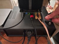
The psu worked out ok. It has a SS relay for the 12V trigger and a trigger bypass switch ( which needs replacing as it is always closed). I used two LRS-200. The KPPX plugs were a bit fiddly to assemble.
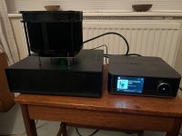
It needs chunkier standoffs as it looks odd.
The fan works really well. The heatsink got to about 60c without it and feels cold with it.
There was a mistake on the silkscreen, RF3 and RF4 were the wrong way round. The fan plug does not have enough room but I bent the pins a little and got it on. The other thing I didn’t take into account was the xlr socket and needed longer standoffs that are used for feet. The diode for the 9V power did not fit the foootprint, it was miles too big!

The psu worked out ok. It has a SS relay for the 12V trigger and a trigger bypass switch ( which needs replacing as it is always closed). I used two LRS-200. The KPPX plugs were a bit fiddly to assemble.

It needs chunkier standoffs as it looks odd.
The fan works really well. The heatsink got to about 60c without it and feels cold with it.
Attachments
Last edited:
Just used the room correction on my WIIM Ultra and it now sounds much better. Not sure what to think of these 3030i speakers, without the room correction it sounds like there is something smothering it slightly. I will drag out my Celestions on the weekend and have a proper listen.
- Home
- Amplifiers
- Pass Labs
- The Holy Grail Follower Output Stage

