At the binding posts, do you have five wires soldered in together or did you use some sort of terminal strip?
I have got round to posting my own build thread. I have put some information on my plan for wiring in one post so that may or may not help
")
http://www.diyaudio.com/forums/full-range/303417-full-range-tc9-line-array-cnc-cabinet.html#post4979544
Sorry for the slight plug but comments are welcome, especially from Byrtt and Wesayso when I get to DSP and measurements.
I don't think he is planning to build arrays, or are you, Pano?
You are correct, I am not building arrays. But I use that driver in a lot of other projects, so any info is welcome. Thanks.
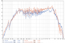
Two reasons posting this data info here, first is because Pano welcome any info for TC9FD18-08, and second is because stumbled over wesayso calling TC9 for 13 years old lady in a PM some time ago and think old lady : ) deserve some praise from time to time, side by side a 6-7 times more expensive 10F/8424 the old lady simply sound and perform great. Both drivers think can do better response and HD than below when their enclosure is more solid and clever constructed in below they were simply non flush mounted on a 160x120cm double layer cardboard baffle, but in conditions were exactly the same think they should be comparable. Had more 2 and 3 incher drivers on that baffle but these two without any correction be it passive or active out of box are the overall best on paper.
Attachments
They are definitely related
Not to talk about how acoustic curves looks and sound in your couch.
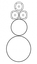
Also had it not be for complicated setup of multiple DAC and numbers of amps guess we could use TC9 in diy mini Beolab 90 clone, below wishful paintbrush is just forward drivers, horizontal arrays are missing
Attachments

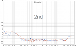
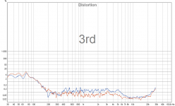
How are those distortion plots generated? Are they close to the max power rating? I wonder if the performance of the TC9 would be even closer to the 10F at lower power, which would be more likely in line array applications. Maybe this is common knowledge that distortion doesn't change with SPL as a percentage of the test signal?
Last edited:
Think of this, whatever level was used in the example from BYRTT, to reach the same level of SPL you'd only need a fraction of that power per driver.
Remember my plots were taken at the listening position, not up close and personal like most people do these charts. They show the results at the spot that matters (to me) and include everything. Even the outside traffic!
Remember my plots were taken at the listening position, not up close and personal like most people do these charts. They show the results at the spot that matters (to me) and include everything. Even the outside traffic!
Agree in array they probably hardly move, its another story that low distortion clean sound will get foot to move some.
Test was early in the morning last weekend and had to work fast measure 8x devices before people upstairs got out of bed and distort measurments, so never had the time to calibrate real spl, but can say it was very uncomfortable levels wearing industrial earmuffs and REW also show curves up higher than i use to see, but for own internal assessment the same condition was the biggest point for test and should be valid comparable.
Test was early in the morning last weekend and had to work fast measure 8x devices before people upstairs got out of bed and distort measurments, so never had the time to calibrate real spl, but can say it was very uncomfortable levels wearing industrial earmuffs and REW also show curves up higher than i use to see, but for own internal assessment the same condition was the biggest point for test and should be valid comparable.

Agree in array they probably hardly move, its another story that low distortion clean sound will get foot to move some.
Test was early in the morning last weekend and had to work fast measure 8x devices before people upstairs got out of bed and distort measurments, so never had the time to calibrate real spl, but can say it was very uncomfortable levels wearing industrial earmuffs and REW also show curves up higher than i use to see, but for own internal assessment the same condition was the biggest point for test and should be valid comparable.
People upstairs still in their bed must love you so much when testing distortion measurements early morning!
Test was early in the morning last weekend and had to work fast measure 8x devices before people upstairs got out of bed
People upstairs still in their bed must love you so much when testing distortion measurements early morning!
Things people do for audio!
People upstairs still in their bed must love you so much when testing distortion measurements early morning!
Things people do for audio!
Can see were we heading with this selfish fanatic audio freak, fortunately he did not line arrays yet
GOODMORNING!!!!!!!!
Trivial version is they live next floor but beds are 2 floor up, so lets stick to above version
.Attachments
Wesayso would you mind expanding on these a little more?
Did you cut the damping to go up to the back of the magnet or even more and then squash it down with the driver?
I really should have though to have a couple of extra pieces cut by the CNC for a test enclosure but it is too late now. Trying to make one is not really on the cards at the moment so I am trying to make a best guess.
How much was overstuffed would you say?
There's still plenty of room between driver and the felt, but yes, there's a quite a fill of fiberglass insulation underneath, the exact amount of it is determined by running impedance tests using my test enclosure.
Did you cut the damping to go up to the back of the magnet or even more and then squash it down with the driver?
I didn't want to guess, but instead use measurements to find out what was needed. The impedance plot can tell you a lot about the success of the internal damping materials. You're not the first to comment on the amount I used though.
I didn't have to stuff it in real tight, but it is quite filled top to bottom. You can actually see when you overfill in the impedance measurements. That takes quite a bit of fill though. I used a paper template to cut the fiberglass in the exact amount as used in the text box. Repeatability is important when building arrays.
I really should have though to have a couple of extra pieces cut by the CNC for a test enclosure but it is too late now. Trying to make one is not really on the cards at the moment so I am trying to make a best guess.
How much was overstuffed would you say?
Wesayso would you mind expanding on these a little more?
Nooo
Did you cut the damping to go up to the back of the magnet or even more and then squash it down with the driver?
No, I cut it into the shape of the chamber and it's clear of the cack of the driver by at least 1.5 to 2 cm. Hard to tell from the picture. The only "slight" compression is top to bottom between my braces.
I really should have though to have a couple of extra pieces cut by the CNC for a test enclosure but it is too late now. Trying to make one is not really on the cards at the moment so I am trying to make a best guess.
How much was overstuffed would you say?
It takes a lot to overstuff. I was interested at what that did for wiggles in the impedance plot. The wool felt is wonderful stuffing, that works really well at mid and high frequencies. I could see the effect on wiggles in the impedance plot and lining all walls helped. The fiberglass fill works to get the impedance peak down and to the left (lower frequency) It should definitely be in the middle of the enclosure and does not need to be directly behind the driver.
I went back trough my pictures. I didn't take one of the fiberglass fill. I guess my fingers itched too much to handle anything
This might help though:

If you look closely you can see there's quite a bit of open space behind the driver. There's wool felt glued on the braces in front of the cover layer of wool felt, it's holding that cover in place.
Here's the total amount of wool felt in each cabinet:

Not shown are the pieces glued to the braces.
And I came across this picture, fun to see the round shape...

If I remember correctly I used 2 layers of fiberglass fill (cut to size) of 6 cm thickness and compressed it between the braces (a less than 8 cm space).
Last edited:
I went back trough my pictures. I didn't take one of the fiberglass fill. I guess my fingers itched too much to handle anything
If you look closely you can see there's quite a bit of open space behind the driver. There's wool felt glued on the braces in front of the cover layer of wool felt, it's holding that cover in place.
If I remember correctly I used 2 layers of fiberglass fill (cut to size) of 6 cm thickness and compressed it between the braces (a less than 8 cm space).
Thanks for the info.
I have been there with fibreglass before, not fun. Nitrile gloves this time and I plan to wrap it up in acrylic damping material, partly because I have a lot of it!
How thick is your wool felt?
I have found some at a reasonable price but it is pretty thin, the stuff used for vehicle underlay.
Mine is ~7 mm thickness. Really remarkable what that 7 mm can do though.
I could maybe use two layers of the stuff I have found to get close. Is there anywhere in the cabinet that you think benefitted the most from the wool in your tests?
Yes, the parts directly near the driver, all walls so to speak. But it also worked better for me to have it around the complete inner walls. In the picture you see a cut out near the driver openings. I tested that, the shape of the brace was shaped there to be thinner.
Like you see here in the picture:

It worked better in impedance tests not to have the felt there, real close but to round it around that opening.
The layer before the fiberglass also had a measurable influence. We are talking about small wiggles here...

One is open baffle, the other two show what adding wool felt did... when carefully setup.
I spend a few days testing this, with all combinations I could think of.
To see how it mattered where to put what, here's the first day also showing wool felt and fiberglass, but not yet optimised:

I also tested all drivers:

Like you see here in the picture:
It worked better in impedance tests not to have the felt there, real close but to round it around that opening.
The layer before the fiberglass also had a measurable influence. We are talking about small wiggles here...
One is open baffle, the other two show what adding wool felt did... when carefully setup.
I spend a few days testing this, with all combinations I could think of.
To see how it mattered where to put what, here's the first day also showing wool felt and fiberglass, but not yet optimised:
I also tested all drivers:
Last edited:
- Home
- Loudspeakers
- Full Range
- The making of: The Two Towers (a 25 driver Full Range line array)