Attachments

I tried to get an idea of the general shape and style I want, based on a lot of searches to find out what I like and dislike in commercial subwoofer shapes and designs.
It would be silly to shape it like my arrays for these lower frequencies. Yet I still want to make it "fit" the general idea. I also like to keep focussed on a functional design, not too much silly stuff. Stylish, timeless and simple if possible. But how much freedom do we have to play with if you go for a ~ 40x40x40 cm box") .
.
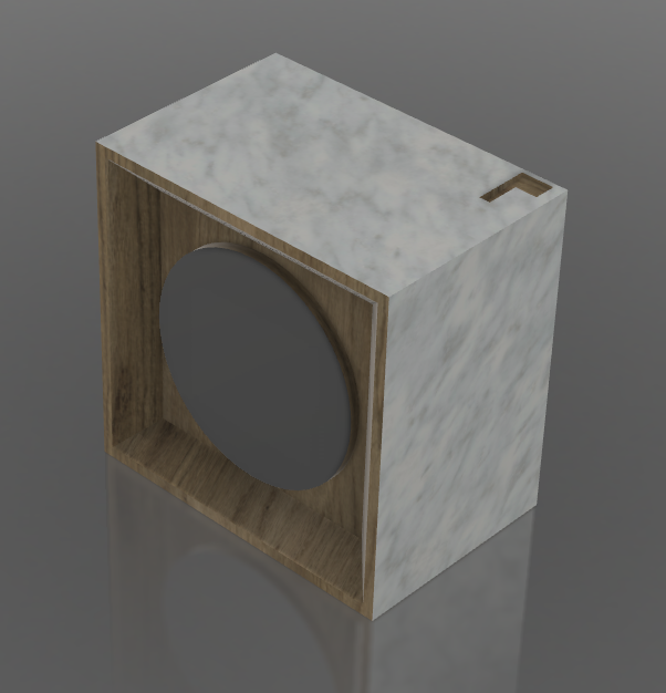
This is the first idea I came up with:

So no huge round overs on this one (it doesn't play high enough for that to make sense). But I did use some round-overs to make it a good fit next to the arrays. More a 'style' thing than pure functional, I admit. Same goes for the back mounted woofer, I like how it looks to tie its design to the the arrays. I don't expect it to add anything to the performance. The inset is chosen to be able to cover it at some point with grill cloth (I'd rather not, but I don't live alone).
As a first idea this works for me. I can't go any bigger. I don't want to go rounder, the ones I found that had big round overs did not look all that stylish to me. So more of an all business look. Still have to work out how I'm going to mount it all without any screws visible, as I do want to keep it maintenance friendly. Yes I do have some ideas for that too. I also need to figure out how to use minimal bracing with maximum effect. Keep as much internal volume as possible while keeping the enclosure dead enough to satisfy me.
Oh boy, I never learn... always rambling on with no end to it...
It would be silly to shape it like my arrays for these lower frequencies. Yet I still want to make it "fit" the general idea. I also like to keep focussed on a functional design, not too much silly stuff. Stylish, timeless and simple if possible. But how much freedom do we have to play with if you go for a ~ 40x40x40 cm box
.This is the first idea I came up with:
So no huge round overs on this one (it doesn't play high enough for that to make sense). But I did use some round-overs to make it a good fit next to the arrays. More a 'style' thing than pure functional, I admit. Same goes for the back mounted woofer, I like how it looks to tie its design to the the arrays. I don't expect it to add anything to the performance. The inset is chosen to be able to cover it at some point with grill cloth (I'd rather not, but I don't live alone).
As a first idea this works for me. I can't go any bigger. I don't want to go rounder, the ones I found that had big round overs did not look all that stylish to me. So more of an all business look. Still have to work out how I'm going to mount it all without any screws visible, as I do want to keep it maintenance friendly. Yes I do have some ideas for that too
. I also need to figure out how to use minimal bracing with maximum effect. Keep as much internal volume as possible while keeping the enclosure dead enough to satisfy me.Oh boy, I never learn... always rambling on with no end to it...

Hahaha, no, this is real time TV... it's going to be slow.
I want to do this once, so I'll try to make sure I do it right.
I've been known to be a little crazy and this little project might prove that's still true.
I don't mind spending extra hours to do things different. I'm even considering using a steel bracing frame, because that would take up less space. I get to practice my welding skills and fire up my welder again. Originally I'm a mechanical engineer, very used to working with metal constructions.
The outside will be birch multiply, I still have some in storage. The inner frame is up for debate. I'll probably line the walls with mass loaded vinyl to get some weight in there.
Wild ideas as usual. I may end up using something more conservative. But at this point basically everything is still up for consideration.
As foolish as ever. When will I learn...
I want to do this once, so I'll try to make sure I do it right.
I've been known to be a little crazy and this little project might prove that's still true.
I don't mind spending extra hours to do things different. I'm even considering using a steel bracing frame, because that would take up less space. I get to practice my welding skills and fire up my welder again. Originally I'm a mechanical engineer, very used to working with metal constructions
.The outside will be birch multiply, I still have some in storage. The inner frame is up for debate. I'll probably line the walls with mass loaded vinyl to get some weight in there.
Wild ideas as usual. I may end up using something more conservative. But at this point basically everything is still up for consideration.
As foolish as ever
. When will I learn...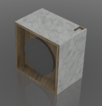
What do you think the crossover point would be? What are you amp plans? I assume JRiver will control everything still?
The amps are still up for debate, no subwoofer specific amp. I need a lot of flexibility.
That brings me to the crossover. I don't plan on using a specific crossover frequency. I consider these subs more like helper woofers. They will play alongside the arrays instead of using the more traditional crossover setup.
The woofers will help me get around room anomalies. So no specific hand over, it's more like a multi sub setup, where the arrays will still play full range and act as (additional) subs while the subs will do most of the hard lifting on the bottom octave.
They will take over the role that each array currently does for the other side.

Left FR and Right FR and sum plotted in one graph
My right array helps out the left at 60-70 Hz. My left array helps out the right array at 30 Hz. With these additional subs that job goes to them. Creating more headroom for the arrays as a side benefit. If I am lucky this will gain me more separation. This will depend on what each sub position can do. The APL_TDA graph I showed here is the left and right speaker working together to get that graph:

The plan is to get a similar result separately for both the left and right side, without needing the output of the "other" array. It won't be easy, but I do like a challenge. Sadly I did not save the APL graphs for a left speaker by itself or the right speaker by itself. The phase plot is telling me enough but a visual reference would have been fun to show.
No doubt JRiver will play a key role here. And DRC-FIR processing.
Last edited:
Wood and Marble?
Not that readily available here
.Also not the look I'm after and I'd hate to try do a round over on that with my hand tools!
I tried to get an idea of the general shape and style I want, based on a lot of searches to find out what I like and dislike in commercial subwoofer shapes and designs.
It would be silly to shape it like my arrays for these lower frequencies. Yet I still want to make it "fit" the general idea. I also like to keep focussed on a functional design, not too much silly stuff. Stylish, timeless and simple if possible. But how much freedom do we have to play with if you go for a ~ 40x40x40 cm box
This is the first idea I came up with:
So no huge round overs on this one (it doesn't play high enough for that to make sense). But I did use some round-overs to make it a good fit next to the arrays. More a 'style' thing than pure functional, I admit. Same goes for the back mounted woofer, I like how it looks to tie its design to the the arrays. I don't expect it to add anything to the performance. The inset is chosen to be able to cover it at some point with grill cloth (I'd rather not, but I don't live alone).
As a first idea this works for me. I can't go any bigger. I don't want to go rounder, the ones I found that had big round overs did not look all that stylish to me. So more of an all business look. Still have to work out how I'm going to mount it all without any screws visible, as I do want to keep it maintenance friendly. Yes I do have some ideas for that too
Oh boy, I never learn... always rambling on with no end to it...
I like the idea about no visible screws, but have concerns about 6 parallel sides of approximately the same size. I have always understood that parallel sides will promote standing waves inside the enclosure, to the detriment of the overall sound produced. Have I understood incorrectly, or will this likely be a non-issue given the limited frequency range these will see?
I like the idea about no visible screws, but have concerns about 6 parallel sides of approximately the same size. I have always understood that parallel sides will promote standing waves inside the enclosure, to the detriment of the overall sound produced. Have I understood incorrectly, or will this likely be a non-issue given the limited frequency range these will see?
That last remark is spot on, we have to consider the lengths of the waves involved for such things to happen. I will use damping inside to limit the effect on the higher frequencies. The side panels will get divided by the braces to prevent them from singing along. They will be placed uneven as to not spur the same frequencies.
I forgot to ask another question... where do you get the 3d digital images of the drivers? These can be very useful to those of us with 3d CAD programs available.
I draw them myself, armed with calipers and other measuring tools.
I've uploaded the 3D model of the Vifa driver, it's linked in this post: http://www.diyaudio.com/forums/full-range/242171-making-two-towers-25-driver-full-range-line-array-187.html#post4617959
Use as is, but please keep the "branding" I put on it on the back side. I may be persuaded to release the subwoofer in a similar fashion. It's the Scan Speak 30W/4558T00.

It's quite a bit of work to get them into CAD, I like to make them as close as I can get them. Drew this one (the W30) on last Sunday's rainy afternoon (over here it was raining).
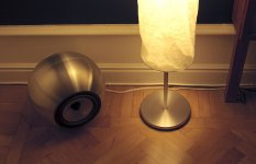
A sphere with mechanically connected driver magnets its the optimal. I built me 2 out of IKEA Blanda Blank (to small for you). B&W makes one.

//
I could not sell that one here
. I don't even want to try! The round shapes B&W got famous for are much more important for mid and higher frequencies. And even those shapes have their limits. My Arrays were build with some inspiration from the B&W's in mind. I doubt it will be of any benefit in subwoofer design, however I am a proponent of using shapes that prevent diffraction as much as possible. No square edges for midrange and above.
Look at the Olson paper, investigating shapes and their effects on wave propagation:

Inner shapes to prevent standing waves would be a different subject. In that view a perfect sphere might not be as ideal if the distances from the back of the speaker start to show similarities and all wall to wall distances are the same. It all depends. Easy to check with impedance measurements though.
The reason for the sphere has noting to do with diffraction. It is the fact that when you pressurise a sphere, the forces on the cabinet will not make it bulge like if it was a box. This is the advantage. If I touch my subs while playing loud, I cant feel any vibration what so ever. To me, this means that what I'm hearing comes form the drivers and not the box. Magnets are glued together.
Attachments
Yes I know pressure vessel theory as my career start was filled with a lot of piping design.
You did notice the arrays go down to 17 Hz, right? Without vibrating the enclosure. Engineering can get you there. Like I said, I can't get away with a shape like that but I do not plan to let vibrations rule.
My arrays were inspected by several people so far, hugging the speakers and putting their ear to it, I should have taken a picture.
Present the impedance curve if you will, always interested to see what a certain design does.
as my career start was filled with a lot of piping design.You did notice the arrays go down to 17 Hz, right? Without vibrating the enclosure. Engineering can get you there. Like I said, I can't get away with a shape like that but I do not plan to let vibrations rule.
My arrays were inspected by several people so far, hugging the speakers and putting their ear to it, I should have taken a picture
.Present the impedance curve if you will, always interested to see what a certain design does.
- Home
- Loudspeakers
- Full Range
- The making of: The Two Towers (a 25 driver Full Range line array)