For bulk capacitance after SLB is there any point in adding bypass cap like you would in a CLC / CRC type power supply?
Bypass caps are only needed to absorb high frequency noise. They don’t hurt but not sure if needed after the SLB.
Hello,
After many hours of drilling / sanding/ finishing work on my wood and metal enclosure for the AN39, I am almost ready to hook up some power and test out the front end transformer/sfp/slb. I would like to test into a load.
I have on hand some 270 ohm/10W resistors which I can sink onto a slab of aluminum or copper. Could these be used, or do I need some other value (ie: less ohms and more wattage) to test/set the slb?.
Thanks for the help.
MM
Myles,
For what amp are you using your SLB for? What is the voltage and current requirement? Have you built that amp already? Do you have a variac?
Another thought if you want to just test the IEC/Transformer/SFP (without the SLB)...do you have an incandescent 60 watt light bulb?
Best,
Anand.
For what amp are you using your SLB for? What is the voltage and current requirement? Have you built that amp already? Do you have a variac?
Another thought if you want to just test the IEC/Transformer/SFP (without the SLB)...do you have an incandescent 60 watt light bulb?
Best,
Anand.
Hello Anand,
It is for the Alpha Nirvana. Have a Variac and a DBT ready. Everything is ready to go.
It is for the Alpha Nirvana. Have a Variac and a DBT ready. Everything is ready to go.
Sorry for misunderstanding.
I'm trying to remember, but I do recall testing my setup with the SLB without a load, and other than the output voltage being a little high (since there wasn't a load), I was able to verify the voltage rails being around +/- 25 to +/- 28V (I had an 800VA Toroidy which has rather good regulation on its own). The reason I did that was to make sure I had connected the BJT's in the capacitance multiplier properly. That's where most builders have trouble, especially with the Molex connectors. I used the knob on my variac to adjust the mains voltage while monitoring the output of the SLB and measured the variability in the DC voltage as expected. That's how I verified that everything was working as expected.
The SLB is basically: Active rectifier -> CRC supply -> capacitance multiplier (with a pot at the end to adjust ripple).
Can you post a picture of your setup starting from Variac to mains IEC to SFP (softstart) to Transformer Primary to Transformer Secondary to SLB?
If you really want to set the pot on the SLB accurately, you want to do it with the actual load along with an oscilloscope looking at the output of the SLB to adjust the pot to the lowest ripple value. That pretty much necessitates a fully built amplifier and would be a last step/tweak to final testing.
But for now, I would double check to make sure your connections are correct for:
Variac to mains IEC to SFP (softstart) to Transformer Primary to Transformer Secondary to SLB.
Best,
Anand.
Last edited:
Thanks for the detail Anand. I was thinking of the no load test also, before I posted about the testing with a load resistor. I will test with no load to confirm the SLB operation. I have traced the Molex connections / traces associated with the BJT's and confirmed with DMM, so hope it goes smoothly. I am using the Antek 4224 transformer and building dual mono.
Since I do not have a scope, I will have to wait until I have attached the amplifier and then do some tweaking to set the ripple at a reasonable level using my DMM.
No problems with Variac to mains IEC to SFP (softstart) to Transformer Primary to Transformer Secondary to SLB, as this how I have set up my FH9 and Xmas amp already and they power up with no problems.
Once I have done the test with no load, I will start installing modules into the enclosure and post some pics at that time. A lot more work to do as I am modeling my own enclosure. Let the fun continue.
MM
Myles,
To test the SLB under load (if more than testing without load is necessary for assurance?) I would suggest using about a 1A load.
So, the math is easy; 25V/1A= 25R load. You'd need about eleven of your resistors all in parallel to get a 25R load.
First check at switch on that the voltage at the output of the SLB is OVER 25V, then hook up the load, when it will drop to about 24-25V. It should not drop more than 2.8V from emitter to collector of the large pass transistor.
Hugh
Hugh and Anand,
Thanks for the help. I am a great builder, but my weakness is testing/troubleshooting due to lack of experience. I think I should have about 34V before rectification and about 28V after.
So after I flick the switch and see what V I have, and, then hook up the 25ohm 50 watt resistor, will the voltage want to keep falling past 25 V?
Also, am I correct in that I can use the test points on the SLB to monitor the voltage drop?
I may have more questions so I am 100% confident in what I am doing.
Yes, it should get close. Remember, the voltage will drop even more in the actual circuit since the current draw is higher. Much of this depends on what your existing secondary voltages are from your transformer and the size of your transformer. Larger transformers are ‘intrinsically’ better regulated so they resist changes in the secondary voltage. In example, I use an 800VA Toroidy which is well designed and keeps those secondary voltages right at 20V AC. As such, whether my circuit has 1.25A current draw or close to 2A of current draw, my rails are at about +/-24 to +/-26V DC.So after I flick the switch and see what V I have, and, then hook up the 25ohm 50 watt resistor, will the voltage want to keep falling past 25 V?
In any case, the Alpha Nirvana circuit works just fine at +/-20V to +/-30V DC so you have loads of leg room.
What Hugh is talking about is measuring across the emitter to collector of the large BJT transistor for each voltage polarity. If you look at the schematic, you will see that the test points (T1, T2, T3, T4) do not measure that. They measure the actual output voltage of each polarity. Checking the voltage across the emitter to collector of the large BJT’s is just an additional step to gain confidence that the circuit is connected and working as it should. There should be no more than a 2.8V drop from emitter to collector. It’s about as simple as that.Also, am I correct in that I can use the test points on the SLB to monitor the voltage drop?
So the only tweaking you will be able to do is adjust the actual output voltage +/- 1V with the pot as designed. That’s about it. A DMM will not show any ripple. You will need a scope to visualize that. Since your Alpha Nirvana will happily work across a wide range of voltage rails (+/-20V to +/-30V DC), it serves as just a tweak, nothing else (making to make the voltages of each potential to be equal, kind of an OCD thing!). For what it’s worth the ripple I have measured has been quite low on the output of the SLB, so honestly speaking the pot could probably be replaced with a fixed resistor in a future rendition of the SLB.Since I do not have a scope, I will have to wait until I have attached the amplifier and then do some tweaking to set the ripple at a reasonable level using my DMM.
I suggest you post pics of what you are doubtful of particularly the wiring. Whenever I have a brand spanking new build, I always use a variac and I always start testing at LOW voltages. With a variac you can vary the mains voltage. Your transformer will work at lower mains voltages just fine. And you can do all this testing without the SFP (sofstart) hooked up since you are confident that it works.
Best,
Anand.
Anand, thank you for the great information. It clears up a lot of confusion on my part. I will proceed with the minor testing I can do, starting with low voltage's.
I will have a DMM measuring across the test points and a DMM measuring from the emitter to collector legs of the BJT's on each polarity. I will test each polarity separately.
Once I have it set up, I will post a pic before initiating testing.
One quick question: Red DMM probe on emitter & black DMM probe on collector, or does it matter ?.
I may take awhile as summer is here and golfing reigns supreme😉
Note: I may have to look into a good quality handheld oscilloscope.
MM
It does not matter because you are just looking at a voltage difference. The voltage difference should be no more than 2.8V.One quick question: Red DMM probe on emitter & black DMM probe on collector, or does it matter ?.
Handheld scopes from OWON like X uses I’ve heard are pretty good.
Best,
Anand.
Greetings,
I had to solder up a new U2 on my SFP and I was not satisfied with the continuity i was getting from the SLB molex boxes to the molex boxes on the BJT helper boards. I changed to soldered ends. I have checked continuity and all is solid.
I think I am ready to apply some power and would like to know if anyone see's something amiss in the pic attached.
One question: Since I have the BJT legs shrink wrapped already, can I attach probes to the appropriate pins in the molex box's (shown with blue tape across open end) to measure the V between the emitter /collector of the BJT's.
Thanks
MM
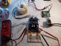

You can, just ensure you don't accidentally have the DMM lead probes slip causing a short.One question: Since I have the BJT legs shrink wrapped already, can I attach probes to the appropriate pins in the molex box's (shown with blue tape across open end) to measure the V between the emitter /collector of the BJT's.
Best,
Anand.
I powered the circuit shown in post #1674, and everything was working fine. The output V varied a bit between 31.3 - 31.9 and the E-C voltage was 2.35V on one side and 2.2V on the otherside.
I powered down the circuit, let the cap's discharge and then started powering back up. When it got to about 40V, I shut off the DBT because I wanted to check something. I came back and switched the DBT back on with the 40V still on the Variac. The SFP board did not like this and the led blinked and the led on my PSU also went dark.
I removed the SFP board, did some voltage checks on the front end and wired the PSU up again. The led's came on and everything looked good. The readings I adjusted to were as follows:
Variac at 115V, output voltage +/- 31.4V, E-C drop 2.3V. Seems good to me.
I will trouble shoot the SFP board. I just put in a new U2, and it was working great. I can rob a SFP from my Xmas amp to use in the meantime to not slow progress down. Now onto to testing the other SLB PSU.
MM
Well not as much luck with the 2nd SLB. When I powered up with the Variac & DBT, I was only able to get to 40V on the variac and the lightbulb was glowing. I shut it down and then just tested the negative side and all I got was -2.36V on the output. The led's did not light.
Not quite sure if I know what is blocking the voltage or what to look for. I have attached a few pic's.
Thanks for any suggestions that would help me out.
MM
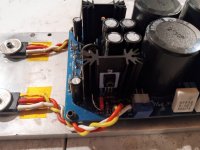
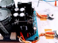
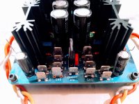
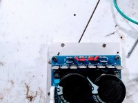
- So what I did was confirm that the transformers were OK. Tested each secondary at 24V on the Antek 4224, so no problems with power to the psu.
- I compared the working SLB with the Non working one, looking at all the components and each resistor to confirm the same. I could not see anything out of place.
- I compared the transistors on the heatsinks and all have the wide flange on the heatsink (123/ECB), so should be correct. The BJT's are all hooked up the same and wired correctly.
- I tested the the 2 green led's with a DMM and they both tested and lit.
Not quite sure if I know what is blocking the voltage or what to look for. I have attached a few pic's.
Thanks for any suggestions that would help me out.
MM


Did you remove the DBT and use just the variac and retest both SLB’s?
Best,
Anand.
Best,
Anand.
Anand,
Since SLB1 tested successfully with the DBT in place, I did not remove it from the test circuit when testing SLB2, the one with problems.
The DBT is glowing brightly when only 40V applied. No smoke or weird pops, click's etc, Just no voltage getting to the output.
I will start by checking/reflowing suspicious solder joints. If this does work, then I will ask for some help with taking some voltage measurements to try and pinpoint the problem.
I have not soldered the heatsinks to the board as I was waiting until after power up to see if any problems. This seemed OK on the successful test of SLB1.
MM
- Home
- Group Buys
- The SLB (Smooth Like Butter) Active Rect/CRC/Cap Mx Class A Power Supply GB