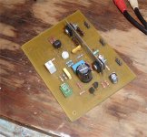
.... I have redraw schematic acording nikosokey implementationhome made case .....
Alex.
D2 cannot be 12V. There is little point running the pre/driver stage at 82VDC and the output stage at 82VDC, the difference has to be about 10V to be of any benefit and drive the MOSFETs to rail.
If the intention is only to make the front end more stable then two diodes would have been enough.
Hi Alex,
I would follow your schematic for the newer pcb version.
Your heatsink seems to be pretty small, sure it is going to be good enough for that?
Any suggestion for alternative for
BD249, BD250
BSS74, BSS71
R20 is 3W, that is pretty big power for a pot (that is for bias adjustment, right?)
BP
I would follow your schematic for the newer pcb version.
Your heatsink seems to be pretty small, sure it is going to be good enough for that?
Any suggestion for alternative for
BD249, BD250
BSS74, BSS71
R20 is 3W, that is pretty big power for a pot (that is for bias adjustment, right?)
BP
A new print for Goldmund clone was purchased some time ago. The original plan was to separate the Protection Part (cutting the PCB) from my "old" print and move it to speaker output.
The purpose was to avoid AC at main PCB. I have previously removed the voltage doubler from the main PCB. My wish was to achieve a main PCB free for AC. This was an object in several discussion early in this thread. Many were sceptical to Alexs final print layout (with AC).
Now, this plan changed when Roar (Malmin) offered me a chassi with transformer and heat sinks. I chosed to use the recently purchased print to adjust my original clone and rebuilt my original to a scaled-down version (a Memesis 3 ?). Pictures will come.
I see that Bigpanda planning a revised edition of the PCB to Memesis 9. I wish I had the same qualifications as Alex to lay out my own prints. With the experience I currently have with Goldmund clone, I would have prioritized the following without deviating much from the original:
1.Use two PCB. The protection part is the one.Mounted at the speaker output
2.A main print that contains a properly regulated and adjustable power supply. I use the proposal on separate print. Such a solution should easily be included on a main PCB.http://www.diyaudio.com/forums/solid-state/185397-building-6-channel-amplifier.html
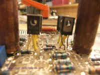
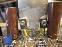
3.Some of use have experienced problems getting stable DC on output. Both Nikosokey and Sng001 have shown concrete solutions by installing T7, 8.9 and 10 on a common cooling plate.
Ostripper has given an explanation of the MPA 42/92 may be replaced by MJE 340/350 and still keep the orginal sound signature. I now use such a solution, but I must adjust to different configuration on the MJE and MPSA (a tricky bending with the legs) I would take this in consideration making a new PCB.
4 A possibility to regulate the current trought the FETs.
Comments from other builders and Bigpanda/Alex
Eivind Stillingen
The purpose was to avoid AC at main PCB. I have previously removed the voltage doubler from the main PCB. My wish was to achieve a main PCB free for AC. This was an object in several discussion early in this thread. Many were sceptical to Alexs final print layout (with AC).
Now, this plan changed when Roar (Malmin) offered me a chassi with transformer and heat sinks. I chosed to use the recently purchased print to adjust my original clone and rebuilt my original to a scaled-down version (a Memesis 3 ?). Pictures will come.
I see that Bigpanda planning a revised edition of the PCB to Memesis 9. I wish I had the same qualifications as Alex to lay out my own prints. With the experience I currently have with Goldmund clone, I would have prioritized the following without deviating much from the original:
1.Use two PCB. The protection part is the one.Mounted at the speaker output
2.A main print that contains a properly regulated and adjustable power supply. I use the proposal on separate print. Such a solution should easily be included on a main PCB.http://www.diyaudio.com/forums/solid-state/185397-building-6-channel-amplifier.html
3.Some of use have experienced problems getting stable DC on output. Both Nikosokey and Sng001 have shown concrete solutions by installing T7, 8.9 and 10 on a common cooling plate.
Ostripper has given an explanation of the MPA 42/92 may be replaced by MJE 340/350 and still keep the orginal sound signature. I now use such a solution, but I must adjust to different configuration on the MJE and MPSA (a tricky bending with the legs) I would take this in consideration making a new PCB.
4 A possibility to regulate the current trought the FETs.
Comments from other builders and Bigpanda/Alex
Eivind Stillingen
Last edited:
Ostripper has given an explanation of the MPA 42/92 may be replaced by MJE 340/350 and still keep the orginal sound signature. I now use such a solution, but I must adjust to different configuration on the MJE and MPSA (a tricky bending with the legs) I would take this in consideration making a new PCB.
Eivind Stillingen
Can you give a link?
Thanks,
- keantoken
mpsa= 40-60Hfe , 40-70mhz Ft, 5-10pF Cob
mje= 40-60Hfe 15-30mhz Ft , 15-20pF Cob
I've used both in my EX voltage stages , did not have to recompensate. Mje's are a little "slower" in simulation but no change in sound.Swapping Ksa/c 1381/3503's to MJE's will change things significantly , the ksa/c's are 150mhz fT with mega Hfe ...150-300.
MJE's are best for 10mA+ higher current VAS's , using a triple OP or other high current gain OP stage , I run to-92 MPSA's at <5ma (super cool). Mje's at 8-12ma will need at least 3 sq. inches of sheet aluminum (below) to keep under 10C above ambient. Couple the whole VAS as one , the thermal coefficients cancel out . That module below just ran flawlessly for 6 months in a sub amp.
OS
mje= 40-60Hfe 15-30mhz Ft , 15-20pF Cob
I've used both in my EX voltage stages , did not have to recompensate. Mje's are a little "slower" in simulation but no change in sound.Swapping Ksa/c 1381/3503's to MJE's will change things significantly , the ksa/c's are 150mhz fT with mega Hfe ...150-300.
MJE's are best for 10mA+ higher current VAS's , using a triple OP or other high current gain OP stage , I run to-92 MPSA's at <5ma (super cool). Mje's at 8-12ma will need at least 3 sq. inches of sheet aluminum (below) to keep under 10C above ambient. Couple the whole VAS as one , the thermal coefficients cancel out
. That module below just ran flawlessly for 6 months in a sub amp. OS
Attachments
Tips for potential builders
Dear all,
I did an google search on "Mimesis 3" & found the following on Nagy's website:
"- Knowleadge in electronics and previous experience in building solid state power amplifiers.
- Must possess the necessary skills to assemble (solder, etc.) a PCB board of over 100 components.
- Must have a way of testing the finished product for oscillations.
- Depending on the chosen grounding scheme and chassis layout and if oscillations are present, the end user must be able to tactically change the values of the small value ceramic discs capacitors (47pF, 10pF, 4.7pF, 8.2pF, etc.), add new capacitors, or subtract the old ones."
I have build Mimesis 3 using Alexmm's PCB & my own PCB; I also experienced some stability problem.
The most critical active components are:
T7, T8 (VAS) - MPSA93 in original Goldmund
T9, T10 (CCS) - MPSA43 in original Goldmund
I have tested the following combinations:
T7,8: Fairchild MPSA92; T9,10: Fairchild MPSA42 - good sound, prone to motorboating.
T7,8: Sanyo A1538; T9,10: Sanyo C3953 - very good treble, not tested for stability.
T7,8: Philips BF470; T9,10: Philips BF469 - Good bass; not tested for stability.
T7,8: Hitachi B1109; T9,10: Hitachi D1609 - good balance sound, unstable - the amp becomes a radio transmitter with square wave at high volume.
The best sounding & stable combination is: T7,8: Fairchild KSP92; T9,10: KTC1027.
The KSP92 has got higher gain than the Fairchild MPSA92 & the KTC1027 has got bigger input capacitance so that the amp is more stable.
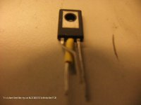
The T7 & T8 are running very hot, the TO92 devices can be 80C above the ambient if they are not attached to a heatsink. I used aradite to glue T7 & T8 to a small piece of aluminum & that bring the temperature down to 42C above ambient.
T11 & T12 - BSS71 & BSS74 in original Goldmund (I used MPSA42/92).
T21 & T22 - BD249 & BD250 in original Goldmund (I used MJE15030/31).
Attached are the measured temperature (ambient = 20C):
T7 & T8 (KSP92 on a common heatsink) = 62C
T9 (KTC1027 with small heatsink) = 44C
T10 (KTC1027 with small heatsink) = 54C
T11 (MPSA42 with small heatsink) = 37C
T12 (MPSA92 with small heatsink) = 39C
When the amp behave, it does sound very good - fast, transparent highs & controlled bass.
If we do a new PCB layout, I suggest to separate the front-end power supply & the protection circuit. The current PCB is simply too big.
Cheers, Stanley
Dear all,
I did an google search on "Mimesis 3" & found the following on Nagy's website:
"- Knowleadge in electronics and previous experience in building solid state power amplifiers.
- Must possess the necessary skills to assemble (solder, etc.) a PCB board of over 100 components.
- Must have a way of testing the finished product for oscillations.
- Depending on the chosen grounding scheme and chassis layout and if oscillations are present, the end user must be able to tactically change the values of the small value ceramic discs capacitors (47pF, 10pF, 4.7pF, 8.2pF, etc.), add new capacitors, or subtract the old ones."
I have build Mimesis 3 using Alexmm's PCB & my own PCB; I also experienced some stability problem.
The most critical active components are:
T7, T8 (VAS) - MPSA93 in original Goldmund
T9, T10 (CCS) - MPSA43 in original Goldmund
I have tested the following combinations:
T7,8: Fairchild MPSA92; T9,10: Fairchild MPSA42 - good sound, prone to motorboating.
T7,8: Sanyo A1538; T9,10: Sanyo C3953 - very good treble, not tested for stability.
T7,8: Philips BF470; T9,10: Philips BF469 - Good bass; not tested for stability.
T7,8: Hitachi B1109; T9,10: Hitachi D1609 - good balance sound, unstable - the amp becomes a radio transmitter with square wave at high volume.
The best sounding & stable combination is: T7,8: Fairchild KSP92; T9,10: KTC1027.
The KSP92 has got higher gain than the Fairchild MPSA92 & the KTC1027 has got bigger input capacitance so that the amp is more stable.
The T7 & T8 are running very hot, the TO92 devices can be 80C above the ambient if they are not attached to a heatsink. I used aradite to glue T7 & T8 to a small piece of aluminum & that bring the temperature down to 42C above ambient.
T11 & T12 - BSS71 & BSS74 in original Goldmund (I used MPSA42/92).
T21 & T22 - BD249 & BD250 in original Goldmund (I used MJE15030/31).
Attached are the measured temperature (ambient = 20C):
T7 & T8 (KSP92 on a common heatsink) = 62C
T9 (KTC1027 with small heatsink) = 44C
T10 (KTC1027 with small heatsink) = 54C
T11 (MPSA42 with small heatsink) = 37C
T12 (MPSA92 with small heatsink) = 39C
When the amp behave, it does sound very good - fast, transparent highs & controlled bass.
If we do a new PCB layout, I suggest to separate the front-end power supply & the protection circuit. The current PCB is simply too big.
Cheers, Stanley
Attachments
Last edited:
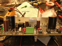
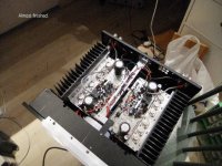
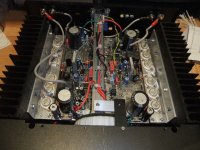
This is my second Goldmund clone.
With a transformer leaving 50 V DC I might call it a Mimesis 3 ?? I use three pairs of FETs instead of two.
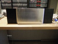
As mention in post 1726 I took over a complete chassis from my friend Roar Malmin (a return for my help to him). PCB fits very well.
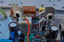
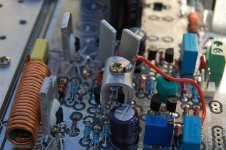
In both my Goldmund clones T7-T10 are now MJE 340/350 monted on a common heatsink (look at # 1652 and # 1728) DC is now low and much more stabel than before. Drivers are also MJE 340/350, but in my Mimesis 9 those drivers are now BSS71/74.
In my scaled down version T1 are 2SK170 BL. I changed R7 to 68 Kohm, R6 to 22 Kohm and R3/4 to 120 ohm. Voltage to the front end are +/- 65 V DC. Works very well.
Both power unit will take place in my rack feeding 50- 500 Hz and 500-20.000Hz. NAD 208 will take care of the sub- bass.Crossover is a very modified DCX 2496. I think I will live happy with this and my Magnepan/NHT 1296 loadspeakers for many years.
Eivind Stillingen
With a transformer leaving 50 V DC I might call it a Mimesis 3 ?? I use three pairs of FETs instead of two.
As mention in post 1726 I took over a complete chassis from my friend Roar Malmin (a return for my help to him). PCB fits very well.
In both my Goldmund clones T7-T10 are now MJE 340/350 monted on a common heatsink (look at # 1652 and # 1728) DC is now low and much more stabel than before. Drivers are also MJE 340/350, but in my Mimesis 9 those drivers are now BSS71/74.
In my scaled down version T1 are 2SK170 BL. I changed R7 to 68 Kohm, R6 to 22 Kohm and R3/4 to 120 ohm. Voltage to the front end are +/- 65 V DC. Works very well.
Both power unit will take place in my rack feeding 50- 500 Hz and 500-20.000Hz. NAD 208 will take care of the sub- bass.Crossover is a very modified DCX 2496. I think I will live happy with this and my Magnepan/NHT 1296 loadspeakers for many years.
Eivind Stillingen
Here are photos
Eivind Stillingen
Eivind Stillingen
Attachments
The best amplifier I have ever heard or I did ever come acorss was the Genesis Stealth B-200.
It had a midrange sweeter than any tube amp and a bass that was deeper and awesome than any Krell amplifier I did ever come across.
In the midrange you could not only hear the musicans breathing, you could hear them wlaking threw the room. At guitar's you could hear the resonance body vibrating when they were playing.
It was the most transparent amplifier I did ever come across. So sad that nobody has the troubleshooting guide with the expected voltages for a repair job that need to be done. Have one here broken. Doesn't turn on :-(
Clearing things up:
Categorized Schematics and Service Manuals for free download
Categorized Schematics and Service Manuals for free download
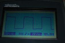
Tomorrow I will add the final touches on the rebuilding of my Goldmund Mimesis 9 clone. What the rebuilding goes on, I have described in #1732
In a private e-mail from my Greek DIYfriend Nikosokey he wrote the following:
"These waveforms you see is a result of some changes
I place a capacitor 100pf/500V mica in parallel with resistors R19 R22 30kΩ 30kΩ"
I am also considering to do this in my Nemisis 9, but wish comments from others who have participated in this thread. Are there any disadvantages of introducing such a mod?
Eivind Stillingen
- Home
- Amplifiers
- Solid State
- The Very Best Amplifier I Have Ever Heard!!!!