I tend to agree. But (I'm not kidding here): There is a little region in the brain called 'nucleus accumbens'. It's very susceptible for e.g. marketing babble and especially for high price tags. It might even let you think you're listening to "The Very Best Amplifier I Have Ever Heard!!!!" (sic).
Hi
I've never had chance to listen to a real one , but I have listened to a cheap clone one and the Leach amp ( use TO3 Transistor ) , I have a feeling this is a winner , If the Leach for me is 8/10 and the clone would be 10/10 , better in the high frequency region , the clone I've listen to used J162 and K1058 with active current source every power Mosfet was driven by a MJE3X0 , and it sounded really good despite it is a cheap clone , there is something with the design of the VAS of this amp
Regards.
The Coloration in Audio Components
The intensive study of several kinds of audio components made by the Goldmund engineers have
proved that most of the audio sonic colorations are due to mechanical vibrations.
If this effect is quite evident for components like speakers or cartridges, the recent research
made by Goldmund on electronics mechanical vibrations is less known.
As for a speaker enclosure that “vibrates”, generating frequency emphasis by re-emission, and
transient blurring by energy absorption, mechanical parts of an electronic circuit, including the
components themselves, can vibrate and generate spurious signal and coloration (usually by
microphonic effect).
The effect is very audible in electronic tubes. When the metallic parts vibrate (and they do when
the voltage applied is modulated by the signal), the resonance of the electrodes themselves
becomes audible, increasing decay time of the signal (the nice “spatial effect” of tubes), and
coloring the signal in some frequency bands depending on the mechanical construction of the
tube (difference between a “good” and a “bad” tube).
“Perfection in an imperfect world”
The effect has also been detected in the past years in capacitors. The so-called “sonic fingerprint”
of capacitors is mostly due to internal vibrations generated inside the capacitors between foils.
The stronger the mechanical assembly is (film and foil Vs electrolytic), and the more “euphonic”
the material resonance is (polystyrene Vs polycarbonate), the “better” the capacitor is for
audiophiles. Thicker dielectric (high voltage) sounds better than finer. Solid aluminum electrolytic
components are used rather than liquid vibrating electrolytic ones, etc…
In an amplifier, the output transistors also generate high levels of vibrations and the Goldmund
amplifiers have started isolating those mechanically from the input circuitry which can capture the
vibrations by the microphonic effect of input transistors.
Mechanical grounding in speakers and turntables can also be improved by a more careful
application of the same principles.
First the mechanical coupling between the component and the earth must be very rigid (thick wire)
otherwise the coupling material itself can resonate and act as a filter (un-damped cones). It will
also transfer less energy (fine wire) and the evacuation of vibrations won’t be perfect.
More, vibrations do travel better from slower material to faster material as we have seen. Proper
selection of materials going from the slower to the faster ensures perfect evacuation and some
limitation of vibration “re-entry” in the component. This effect has been called by Goldmund the
“Mechanical Diode” effect. As seen in the optical analogy, the angles of the different mechanical
parts attached together have some effect on this capability of directionality. It is interesting to
notice that the cone is the shape used to represent a diode in electronics
--------------------------------------------------------------------------------------------------------------------------------
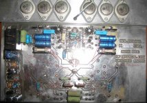
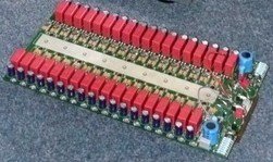
Based on this photograph we see that all the electrolytic capacitors and other materials diode main reservoir electrolytic capacitors 4700μf are joined to a thin line
ground PSU .
The intensive study of several kinds of audio components made by the Goldmund engineers have
proved that most of the audio sonic colorations are due to mechanical vibrations.
If this effect is quite evident for components like speakers or cartridges, the recent research
made by Goldmund on electronics mechanical vibrations is less known.
As for a speaker enclosure that “vibrates”, generating frequency emphasis by re-emission, and
transient blurring by energy absorption, mechanical parts of an electronic circuit, including the
components themselves, can vibrate and generate spurious signal and coloration (usually by
microphonic effect).
The effect is very audible in electronic tubes. When the metallic parts vibrate (and they do when
the voltage applied is modulated by the signal), the resonance of the electrodes themselves
becomes audible, increasing decay time of the signal (the nice “spatial effect” of tubes), and
coloring the signal in some frequency bands depending on the mechanical construction of the
tube (difference between a “good” and a “bad” tube).
“Perfection in an imperfect world”
The effect has also been detected in the past years in capacitors. The so-called “sonic fingerprint”
of capacitors is mostly due to internal vibrations generated inside the capacitors between foils.
The stronger the mechanical assembly is (film and foil Vs electrolytic), and the more “euphonic”
the material resonance is (polystyrene Vs polycarbonate), the “better” the capacitor is for
audiophiles. Thicker dielectric (high voltage) sounds better than finer. Solid aluminum electrolytic
components are used rather than liquid vibrating electrolytic ones, etc…
In an amplifier, the output transistors also generate high levels of vibrations and the Goldmund
amplifiers have started isolating those mechanically from the input circuitry which can capture the
vibrations by the microphonic effect of input transistors.
Mechanical grounding in speakers and turntables can also be improved by a more careful
application of the same principles.
First the mechanical coupling between the component and the earth must be very rigid (thick wire)
otherwise the coupling material itself can resonate and act as a filter (un-damped cones). It will
also transfer less energy (fine wire) and the evacuation of vibrations won’t be perfect.
More, vibrations do travel better from slower material to faster material as we have seen. Proper
selection of materials going from the slower to the faster ensures perfect evacuation and some
limitation of vibration “re-entry” in the component. This effect has been called by Goldmund the
“Mechanical Diode” effect. As seen in the optical analogy, the angles of the different mechanical
parts attached together have some effect on this capability of directionality. It is interesting to
notice that the cone is the shape used to represent a diode in electronics
--------------------------------------------------------------------------------------------------------------------------------
Based on this photograph we see that all the electrolytic capacitors and other materials diode main reservoir electrolytic capacitors 4700μf are joined to a thin line
ground PSU .
Attachments
Last edited:

Based on this photograph we see that all the electrolytic capacitors and other materials diode main reservoir electrolytic capacitors 4700μf are joined to a thin line
ground PSU .
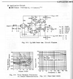
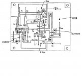
Yes, it is a star ground arrangement. That is also described in the Hitachi application note. It suppose to prevent +/- line unbalance. However Hitachis "standard" printed layout in the application note follows HF design topology PCBs. They may have obtain a design less prone to oscillate that way. Hitachi actually states that "in this high negative feedback amplifier, caution must be taken to avoid oscillation which depends on the printed pattern".
Last edited:
Is the Hitachi application note available?
Thanks
Attachments
http://www.diybanter.com/attachment...mosfet_appnote-pdf-hitachi_mosfet_appnote-pdf
(fresh&unmarked scanned copies will cost you cold hard cash. )
)
(fresh&unmarked scanned copies will cost you cold hard cash.
)Thanks to both of you. For myself, I see I have opened a bag of worms (or jellybeans). It seems, as usual, ask here and be ready to be hit with a ocean of information. I have got to do some reading on this situation, to say the least. WOW!!!
How much to keep my old and decrepit eyes from turning over and over in their sockets with a FrEsH copy?
I am doing a board, and I want to get it right from the beginning
Again, Thanks
How much to keep my old and decrepit eyes from turning over and over in their sockets with a FrEsH copy?
I am doing a board, and I want to get it right from the beginning
Again, Thanks
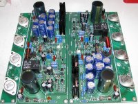
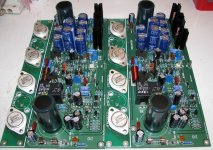
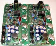
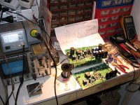
Hi Alex.... not finished , missing some parts (resistors) but here are few pictures with my second Goldmund clone amplifier....
Alex.
Congratulate you have very nice KIT.
I have clone many Goldmund amplifier circuit
My experience,have two ways to have great sound with Goldmund circuit(lateral mosfet output) is:
1. High current bias(200-300mA), with power supply enough clean (large capacitance>10.000uF or parallel multiple small capacitors),it raises more heat,heatsink must be large enough.Goldmund does not choose.
2. Low current bias(70-90mA), the power supply does not need too clean(for Power Amplifier stage - Output).Goldmund has chosen this option,so they just choose capacitors for the power supply is 2200uF +1000uF = 3300uF.Their heatsink is very small.
Because the small capacitance means is the impedance power supply will be greater,it raises many harmonic distortion on the load speakers, when considering the load resistor to announce the results, it is very low harmonic distortion but the reality is not so, the speaker is not the same as resistance.
Sounds great,to less expensive materials,structure machine not bulky,be durable by very low-temperature,little damage, very aesthetic,...
This is secret Goldmund's
Last edited:
Metis3 used 3300uF/100V/one chanel ( main power supply for output stage,Vas,input,...)
T5000 use 18x100uF = 1.800uF/one chanel(power supply for output stage),not large capacitor after diode rectifier.
T5000 use 2x4700uF + voltage regulator circuit super-linear for Vas,Input,...
T5000 use 18x100uF = 1.800uF/one chanel(power supply for output stage),not large capacitor after diode rectifier.
T5000 use 2x4700uF + voltage regulator circuit super-linear for Vas,Input,...
Attachments
Metis3 used 3300uF/100V/one chanel ( main power supply for output stage,Vas,input,...)
T5000 use 18x100uF = 1.800uF/one chanel(power supply for output stage),not large capacitor after diode rectifier.
T5000 use 2x4700uF + voltage regulator circuit super-linear for Vas,Input,...
Telos 5000 uses 24 pices of 10000uF capacitors for one channel output stage, see picture from factory.
Attachments

Telos 5000 uses 24 pices of 10000uF capacitors for one channel output stage, see picture from factory.
No,In the schematic and part list and layout of T5000 is not so many
Here
In main power supply not large capacitor
In output stage not large capacitor
Attachments
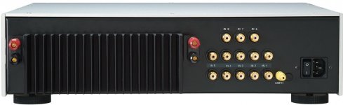
This is from goldmund Telos 5000 sales leaflet:
Output Circuit
The Output Circuit uses an incredible 72 Power Mosfets,
which have been specially calibrated for the Telos 5000.
A NEW type of cascade/bridged circuit increases the
amplifier’s speed above anything ever achieved, even in
the other Goldmund Telos amplifiers.
It is powered by a phenomenal stack of 24 huge ultralow
impedance filtering capacitors, which again are
designed specifically for the Telos 5000 with a total value
approaching 0.2 Farads
It can be read here:
http://www.symmetry-systems.co.uk/Images/pdfs/SYMM-Telos-5000-v2.pdf
It is used 72 mosfets,the connection type BTL- 18 pairs/1 branch.This is from goldmund Telos 5000 sales leaflet:
Output Circuit
The Output Circuit uses an incredible 72 Power Mosfets,
which have been specially calibrated for the Telos 5000.
A NEW type of cascade/bridged circuit increases the
amplifier’s speed above anything ever achieved, even in
the other Goldmund Telos amplifiers.
It is powered by a phenomenal stack of 24 huge ultralow
impedance filtering capacitors, which again are
designed specifically for the Telos 5000 with a total value
approaching 0.2 Farads
It can be read here:
http://www.symmetry-systems.co.uk/Images/pdfs/SYMM-Telos-5000-v2.pdf
My picture show is 1 branch,it is only 2x18pcs capacitors/1branch only, no place other has the power capacitor.
I have documents about t5000 is full(schematic,layout,part list) and it does not have to 0.2Farad.
Hix,I done know manufacturers have announced true design or this is maketing
My picture show
Mr Nguyen seems to have good resources.
Attachments
- Home
- Amplifiers
- Solid State
- The Very Best Amplifier I Have Ever Heard!!!!