Looks very good.. similar L(f) to 22.579MHz Pulsar Clock from 1Hz to 10Hz, and proabably a lot less expensive!.
Can you measure below 1Hz?..
More expensive I would think. My selected NDKs for 20usd a pop. Iäm now going to build something from Andrea...
//
Attachments

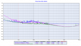
And now a few comparison of the phase noise plots:
- Fifo MCLK Out Crystek vs Driscoll
- Fifo SCK Out RPI vs Crystek vs Driscoll
- Fifo LRCK Out RPI vs Crystek vs Driscoll
The plots tell themselves, so better if avoid any comment.
Maybe the designer could comment the measurements.
I only have to say that the Crystek is 26dB worse than the Driscoll at 10Hz from the carrier, as expected.
There was an error in the plots, I have published the same LRCK plot 2 times instead of the SCK one.
I attach the corrected plots.
Attachments


Thans Andrea, Those plots have been very helpful getting a better insight what is going on.
Two things popped out for me. I might be wrong in this so happy to learn.
1
As the PCM1794 does the conversion at BCK / SCK this is what I looked for in your plots. I see that the Driscoll is like 10 dB better at 10 Hz and after that it is almost similar.
2. The MCK from the FiFoPi is a direct measurement from the clock, whereas the SCK went through the On board logic. Jitter is introduced in this process.
I am still not sure, what impacts the perceived gain of sound quality more, the 10Hz or the 100 Hz spec... I believe I recall that by experiments done, it was round the 100 Hz mark. But I might be wrong.
Not sure I can do anything with this information, other than trying to correlate what I hear on sound reproduction with and without fifopi and the kind of clocks used and as said, how that correlates...
You have always to look at the close in phase noise, around 10 Hz or lower from the carrier, since the short term stability is the most important factor in digital audio.
The MCK was measured at the output of the FifoPi, I don't know how the FifoPi manages the MCK.
I could imagin that it crosses a multiplexer.
I said I would avoid commenting, I wouldn't want to be burned at the stake of fundamentalist followers, anyway it looks like the jitter won the battle against the ultimate weapon.
About the SCK output one would expect a phase noise 6 dB better than the MCLK since the MCLK is divided by 2. Unfortunately:
- at 1 Hz from the carrier the SCK is 10 dB worse than the MCLK
- at 10 Hz from the carrier the SCK is 9 dB worse than the MCLK
- the broadband noise of the SCK is around 20 dB worse than the MCLK
- in both SCK and LRCK plots there is a noise peak in the range 30-300 Hz.
The LRCK output is even worse, in that case we are dividing down several times, so one expects a great improvement, instead:
- the noise peak is more pronounced
- at 10 Hz from the carrier the phase noise is almost the same of the RPI with the Driscoll oscillator and 4 dB worse than the RPI with the Crystek oscillator
- the broadband noise is a disaster related to the MCLK
Keep in mind that I have measured -132 dBc at 10 Hz from the carrier of a cheap DDS signal generator at 192kHz.
Not a big surprise for me, the measurements confirm what I suspected.
A couple of year ago I built an audio system for a friend using the FIFO buffer and the old Driscoll oscillator with the SC-Cut crystal at 11.2896 MHz.
The source is a SD card player microcontroller based.
When I did listen the first time I was disappointed, the sound was harsh, the soundstage was compressed, the voices was unreal.
So I did look at the source and I discovered it use a cheap chinese oscillator at 22.5792 MHz. Initially I was not worry about the source because I expected that the FIFO removing the jitter of the source.
Then I replaced the cheap oscillator of the source with a better one (nothing special, the old Pierce pico gate) and the sound changed dramatically.
Real voices, smooth sound, wide soundstage and so on.
What does it mean?
It does mean that the FIFO buffer is source dependent, it does not remove all the noise coming from the source, part of the source noise is reflected to the output.
Finally, how can you correlate the measurements with the sound?
Since you are using the PCM1794 that switches on the BCK signal you can expect an improvement in sound using the FIFO with a fine oscillator.
If you look at the SCK output comparison plot you can see that the SCK is 8-9 dB better than the original from the RPI with the Crystek, and 22-23 dB better with the Driscoll at 1 Hz from the carrier.
At 10 Hz from the carrier the SCK output has almost the same phase noise of the RPI, while it's almost 16 dB better with the Driscoll.
Certainly it's not the best you could reach, we are far away from a very good digital chain.
But as I said this is another story, this is not the "ultimate" way to get the best performance.
I pointed out several times what is wrong in the architecture, starting from the stacked devices, that's a great error.
I believe I have wrote too much, I hope this helps to understand what are the crucial aspects of a digital chain, now it's the time to come back to my designs.
More expensive I would think. My selected NDKs for 20usd a pop. Iäm now going to build something from Andrea...
//
Not exactly, the Pulsar clock is a 350 EUR device, the New Driscoll at the same 22.5792 MHz frequency is less than half price and has 5-6 dB better close in phase noise.
Obviously you can get a toy for 20 USD. And you can save 10 USD more using the Si570.
It depends on what are you looking for.
So, yes, the Pulsar is more expensive. I would say that my NDK is between the toys and you clocks.
//
//
I would say nearer to the toys rather than the SOTA oscillators, since NDK sells its DuCuLoN at around 1600 EUR.
I drive the Ian's FIFO reclock with the old Driscoll XO, before it I used the NDK NZ2520. The Driscoll was a big upgrade. The new Driscoll will be an upgrade from old, I think, but IMHO it will be less improvement jumping than before.
And now a few comparison of the phase noise plots:
- Fifo MCLK Out Crystek vs Driscoll
- Fifo SCK Out RPI vs Crystek vs Driscoll
- Fifo LRCK Out RPI vs Crystek vs Driscoll
The plots tell themselves, so better if avoid any comment.
Maybe the designer could comment the measurements.
I only have to say that the Crystek is 26dB worse than the Driscoll at 10Hz from the carrier, as expected.
Andrea, a I understand it, two more measurements will be added to these measurements soon? :
- Fifo SCK Out RPI with OCXO vs Crystek vs Driscoll
- Fifo LRCK Out RPI with OCXO vs Crystek vs Driscoll
These will be two very interesting graphs 🙂
Oleg
And now a few comparison of the phase noise plots:
- Fifo MCLK Out Crystek vs Driscoll
- Fifo SCK Out RPI vs Crystek vs Driscoll
- Fifo LRCK Out RPI vs Crystek vs Driscoll
The plots tell themselves, so better if avoid any comment.
Maybe the designer could comment the measurements.
I only have to say that the Crystek is 26dB worse than the Driscoll at 10Hz from the carrier, as expected.
thank you for the interesting measurements!
I would like to ask you the photo of the experiment - I would like to understand and see how everything is connected?
did you use builtin isolator?
Andrea, a I understand it, two more measurements will be added to these measurements soon? :
- Fifo SCK Out RPI with OCXO vs Crystek vs Driscoll
- Fifo LRCK Out RPI with OCXO vs Crystek vs Driscoll
These will be two very interesting graphs 🙂
Oleg
Already published, please see post #2403
thank you for the interesting measurements!
I would like to ask you the photo of the experiment - I would like to understand and see how everything is connected?
did you use builtin isolator?
I have used a Raspberry PI 3 with stacked ReceiverPi and FifoPi.
I followed the suggestion of the designer stacking all the devices, that's not a good practice as I said several times.
Oscillators used for the measurements are the Crystek CCHD-957 at 24.576 Mhz and my new Dricoll oscillator at 22.5792 MHz.
Sorry, I have no pictures and all the stuff are already inside a package to be returned back to the member who send me them.
I have said several times that jitter is a standalone number that does not say anything because it does not explain the spectrum of the noise. It's a valid measurement results for telecommunication but not for digital audio.
BTW I attach some phase noise plots from real measurements and RMS jitter conversions to better understand the importance of the noise spectrum.
The title of each picture refers to the measured device.
Sorry but I have no time to comment the measurements, maybe later.
P.S.
Anyway your calculated 3.12ps or my calculated 2.656ps from real measurements for the Crystek CCHD-957 means that the members got a crappy oscillators, real low noise oscilaltors are in the fS region.
I wonder how one could think to get a good oscillator for 25 Euro.
@andrea_mori
Thank you for posting the phase noise testing result. The 24.576 MHz (MCLK) and 12.288MHZ (SCK) measurements are very close to my time domain jitter test result. You did a good job.
But I don't think your low frequency 192KHz LRCK phase jitter testing result is correct. Low frequency clock measurement is really challenging to a phase noise analyzer. However, your TimePod may even not be capable of the192KHz measurement. You also forgot to mention to us that the TimePod has limitations to measure frequency lower than 0.5MHz and higher than 30MHz. 192KHz LRCK is already out of the testing range. No matter how you implemented the measurement, How can you keep accuracy for an out of range measurement? How about the change on phase noise floor? How to calibrate, How to validate the testing result.... All of those have to be questioned before you post the result.
Basically the FifoPi I2S jiitter will be MCLK jitter + additive jitter of the flip-flop. SCK and LRCK are both slaved to the same MCLK , and from the same flip-flop package. So, the jitter of FifoPi LRCK will be exactly the same as SCK. Since your FifoPi SCK phase jitter test result was RMS 3.103ps, the LRCK phase jitter should be around RMS 3.103ps too. My time domain jitter test result also supports this. However, your 192KHz LRCK phase jitter testing result is way off compared to this number and also my time jitter testing result. That's very unreasonable. How can we trust your phase phase noise and phase jitter measures at low frequency?
Why don't you measure the SCK and LRCK of a 44.1KHz 16bit music? I was wondering if I can use phase noise to discuss the I2S signal, but finally found it's impossible. Even yourself have to convert the phase noise into phase jitter for the I2S testing result. BTW, as long as you use RMS for jitter number, it means the jitter is not just a number. Actually each point of the time jitter histogram curve is corresponding to an offset frequency at phase noise plot.
I can post my time domain FifoPi jitter testing result for you to reference if you want .
Regards,
Ian
The lower limit of the Timepod, as I have already said, is imposed by software (TimeLab) and can be bypassed, the only hardware limit is the input transformer that's specified in Mini-Circuits datasheet as 0.05 MHz, so there is no issue to measure down to 88.2 kHz (we have chosen prudentially 176.4 kHz).
If you know how Timepod works, its ADC has no problem to convert down to 100 kHz or below, simply the software needs more samples to perform an accurate measurement at lower frequencies.
And thanks to cross-correlation, there is also another way to measure down to almost DC: an RF mixer to sum the frequency of the reference (in the Timepod range) with the frequency of the DUT (192 kHz or lower). The cross-correlation remove the noise of the reference and finally measure the DUT. That's the reason why we was able to measure -157 dBc at 10 Hz from the carrier with a worse reference (the MTI has around -140 dBc at 10 Hz from the carrier).
Moreover, we have asked the designer before the measurement, and he had confirmed that there is no issue to measure down to 100 kHz, the limit is the input transformer
The validation comes from a cheap Rigol DG1022 DDS signal generator measurement, that showed -132 dBc at 10 Hz from the carrier at 192 kHz.
I can't imagine that the Timepod would penalize your devices against other DUTs.
So your questions was answered before measuring and publishing.
Well, if the FifoPi performs 7dB worse than the Rigol with a true low noise oscillator (the Driscoll) and 10 dB worse than the DDS generator with the Crystek oscillator, and even worse than the original BCK from the Raspberry (4 dB with the Crystek), I believe that you should ask yourself several questions.
Are you sure that FifoPi I2S jitter should be BCLK jitter + additive jitter of the flip-flop?
Firstly, each time you divide you should theoretically improve the phase noise for 6 dB, so SCK and mostly LRCK should have a lower phase noise than the MCLK.
Then, I have never seen any schematic of your devices, but I assume that the SCK and the LRCK are generated inside the FPGA. How about the firmware?
Again, I don't know anything about the firmware, but I suspect there is something not well optimized since the broadband noise rises a bit (maybe crosstalk?).
I have converted the phase noise into phase jitter only because you continue to ask for this number, that's a valid result for telecommunications but useless in digital audio.
As you can see from the plots the phase noise analysis shows perfectly the spectrum of the noise, and regardless of the jitter measurement there is a clearly visible peak of noise in the range 30 to 300Hz.
And it does not come from the master clock and neither from the Raspberry.
These plots can help you a lot to improve your devices, now you know exacty where you have to put your hands.
Andrea
@andrea_mori
"The lower limit of the Timepod, as I have already said, is imposed by software (TimeLab) and can be bypassed"
I don't think you can keep the accuracy and noise floor if you hack the low limitation. The fact is that within 0.5MHz to 30MHz working range, your measurements are quite accuracy. But it becomes way off if the frequency is out of this testing range.
"The validation comes from a cheap Rigol DG1022 DDS signal generator measurement"
Did you lower your TimPod reference clock by a cheap DDS? That's the most significant part of the phase noise measurement.
"Firstly, each time you divide you should theoretically improve the phase noise for 6 dB"
If you have high speed logic design experience, you should know that there is no ideal clock divider in the real world. All clock dividers have additive jitter. A good clock divider normally have a couple of ps of additional jitter. So, 6dB doesn't exist in the real world.
"Are you sure that FifoPi I2S jitter should be BCLK jitter + additive jitter of the flip-flop?"
FifoPi generates both SCK and LRCK at finial flip-flops in clock section by the MCLK. Fifo logic (FPGA) only makes them synchronized to the new MCLK domain (to perform clock domain isolation). Has nothing to do with firmware. So, why not?
"Well, if the FifoPi performs 7dB worse than the Rigol with a true low noise oscillator (the Driscoll) and 10 dB worse than the DDS generator with the Crystek oscillator, and even worse than the original BCK from the Raspberry (4 dB with the Crystek)"
If the measurement result is not reliable then everything could be wrong. And also I2S are square wave digital signals, you need to measure the jitter of the rising edges of the signals. That could be another limitation of phase noise measurement.
Regards,
Ian
Last edited:

@ Bisesik
😉 I like your smiley icon...
but in all seriousness, I do like the discussions between Ian and Andrea, as I learn a lot extra about all the aspects of phase noise and jitter. So I certainly welcome this.
I hope the tone stays ok (even though I did not like so much the "fundamentalist" comments from Andrea, but ok, I am a big boy, so can handle that)
On the topic itself. I mentioned already, the only thing which counts for me (and many other DAC chips) is the BCK/SCK signal - so the LR jitter is of little importance - even though I like the discussion why the differences are as they are between the two measurements.
And it seems, that there is, next to the audible (!) improvement using the fifopi with relatively good clocks like Accusilicon (even though they are called toys), room for improvement with clocks which are better thanks to taking care of crucial design elements.
Supersurfer also mentioned the improvement using Andrea's previuos clocks with fifopi and the DDDAC 1794 dac setup
so my Question to Andrea would be if he could advise what someone would need to buy from your group buy to be used in the FiFoPi as a complete best possible set assuming one would like to play up to 192kHz tracks ?
that would be nice
@andrea_mori
"The lower limit of the Timepod, as I have already said, is imposed by software (TimeLab) and can be bypassed"
I don't think you can keep the accuracy and noise floor if you hack the low limitation. The fact is that within 0.5MHz to 30MHz working range, your measurements are quite accuracy. But it becomes way off if the frequency is out of this testing range.
"The validation comes from a cheap Rigol DG1022 DDS signal generator measurement"
Did you lower your TimPod reference clock by a cheap DDS? That's the most significant part of the phase noise measurement.
"Firstly, each time you divide you should theoretically improve the phase noise for 6 dB"
If you have high speed logic design experience, you should know that there is no ideal clock divider in the real world. All clock dividers have additive jitter. A good clock divider normally have a couple of ps of additional jitter. So, 6dB doesn't exist in the real world.
"Are you sure that FifoPi I2S jitter should be BCLK jitter + additive jitter of the flip-flop?"
FifoPi generates both SCK and LRCK at finial flip-flops in clock section by the MCLK. Fifo logic (FPGA) only makes them synchronized to the new MCLK domain (to perform clock domain isolation). Has nothing to do with firmware. So, why not?
"Well, if the FifoPi performs 7dB worse than the Rigol with a true low noise oscillator (the Driscoll) and 10 dB worse than the DDS generator with the Crystek oscillator, and even worse than the original BCK from the Raspberry (4 dB with the Crystek)"
If the measurement result is not reliable then everything could be wrong. And also I2S are square wave digital signals, you need to measure the jitter of the rising edges of the signals. That could be another limitation of phase noise measurement.
Regards,
Ian
It looks like you don't know how a phase noise analyzer such the Timepod or the E5052 works, I would suggest Time-Nuts forum and Rubiola.org.
We have not hacking anything, simply there is an option in the software to remove the lower limitation.
So, the measurements of the Timepod are not "quite accuracy", they are the same of the Aeroflex PN9000 and the Agilent E5052A. We have measured the same devices and the phase noise plots are exactly the same for all the gears.
The cheap DDS was the DUT not the reference! The reference are a couple of MTI 260 OCXO, used in 3 cornered hat measurement.
The cheap DDS, the DUT, was measured with square wave ouptut at 192 kHz, the measured phase noise at 10 Hz from the carrier was -132dBc, while the phase noise of the LRCK from the FifoPi at the same frequency is -125dBc at 10 Hz from the carrier, 7 dB worse.
So do you think that the Timepod penalize the FifoPi?
"If you have high speed logic design experience"... I have no experience of anything, I am a beginner who likes to measure rather than claim.
"A good clock divider normally have a couple of ps of additional jitter." Although you continue to talk about jitter, it's not true, a good divider does not add any jitter/phase noise, when you divide you should improve the close in phase noise, otherwise there is something wrong.
The problem here is that your divided clock is worse than the MCK to be divided. Please, take a look at the SCK comparison plot #2398, the MCLK (22.5795 MHz) is -126.2 dBc while the FifoPi output (11.2896 MHz) is -117.7 dBc, 8.5 dBc worse.
The measurement results are more than reliable and the phase noise analyzer ha no problem to measure the phase noise of a square wave. Please, compare the first plot in post #2398 with the plot #2017, the plots are almost identical.
The older is the phase noise of the sine wave output of the Driscoll oscillator at 22.5792MHz, the newer is the same oscillator followed by a squarer.
You continue questioning the reliability of the LRCK measurement, especially the noise floor, when the SCK measurement is even worse.
Do you trust the reliability of the Timepod at 12MHz?
Please, take a look at the second and third plots in post #2395:
- 100 Hz from the carrier, FifoPi LRCK is -120dBc, while FifoPi BCK is -116dBc, 4 db worse
- 1kHz from the carrier, FifoPi LRCK is -130dBc, while FifoPi BACK is -126dBc, again 4 db worse
- 10kHz from the carrier, FifoPi LRCK is -140dBc, while FifoPi BACK is -133dBc, 7 db worse
- 100kHz from the carrier, FifoPi LRCK is -136dBc, while FifoPi BACK is -134dBc, 2 db worse
So the noise floor of the FifoPi BCK at 12.288MHz is far worse than the noise floor of the crappy Crystek.
Do you think the Timepod adds 20-25 dB to the noise floor of the FifoPi BCK?
Now take a look at the attached picture, it shows the LRCK output of the FifoPi.
It looks like you have crosstalk.
Finally, I believe this discussion is off topic in this thread, you should copy all the plots in the FifoPi thread and continue the discussion there.
Andrea
Attachments

- Status
- Not open for further replies.
- Home
- Source & Line
- Digital Line Level
- The Well Tempered Master Clock - Building a low phase noise/jitter crystal oscillator