X Thanks for the explanation. For my part, I understand that using Talema 70052k 12v + 12v (+/- 18v output) I will have to bridge and leave the 24v (+ 34v) output winding in series. I will try to play with the potentiometers on the Yarra PSU and the R121 / 122 resistors on the Hakuin pcb, adjusting the closest to + 24v.


12v x 1.41 = 16.8v
Then you have to account for the capacitance multiplier voltage drop. The better option is a Talema 22v trafo.
Blocked
Using the higher voltage transformers will give you more options with your daughter board choices. Using a 12v transformer will not get the output voltage your looking for.
Also, The trimpots in the PSU section have very little effect over output voltage, probably less than 1v.
Thanks Vunce! It seems the best option. I realized late and ordered the wrong Talemas ... Too bad!
Greeting
Greeting
Hello,
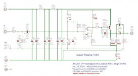
I am finally getting around to putting together my Hakuin boards that will go on a fully loaded up Yarra motherboard, using 2SK170BL and 2SA1837. I would like to verify that, in this configuration, it is ok to leave the following components unpopulated on the Hakuin boards:
R101, R102, R114
C101, C102, C103, C104, C113, C114
V102, V111
Thanks,
Alan
Aljordan and Karucho,
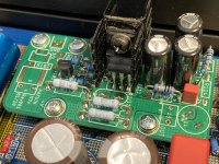
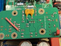
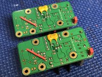
It’s a good thing I refreshed the page before I sent my post! I was re-sending the same pictures you just posted to show the configuration of my Hakuin boards, LOL!!
Correct setup AJ.
Don’t forget to add two jumpers:
C104 —>R101
Short C114
It’s a good thing I refreshed the page before I sent my post! I was re-sending the same pictures you just posted to show the configuration of my Hakuin boards, LOL!!
Correct setup AJ.
Don’t forget to add two jumpers:
C104 —>R101
Short C114
Last edited:
Start with 22R and increase to drop the output voltage to the Hakuin. Ideally, adjust so that the value of voltage at the collector of the 2SA1837 BJT circa 24v +/-2v is ok.
Hi,
I built my Hakuin boards according to the resistor values in the schematic in post 1404, using 22R for R121 and R122. According to the 2SA1837 data sheet, the collector is the center post of the device. I hooked boards up to a lab power supply set at 24 volts, and measured voltage at the center pin of the 2SA1837 to ground, and I am only seeing ~12.8 volts. The other pins are seeing about 20 volts.
Am I measuring the wrong pin, or did I do something drastically wrong?
Thanks,
Alan
The emitter (pin3) will see the voltage right after the CRCRC.
My setup measurements:
Input V+ = 23.90v
B = 23.09v
C = 15.28v
E = 23.72v
AJ, my power supply outputs 24v, So I do not have to drop any voltage on the Hakuin Board, I have paralleled resistors for only 1R at R121 and R122.
If you are feeding your Hakuin with 24v also, drop the 22R’s to 1R
My setup measurements:
Input V+ = 23.90v
B = 23.09v
C = 15.28v
E = 23.72v
AJ, my power supply outputs 24v, So I do not have to drop any voltage on the Hakuin Board, I have paralleled resistors for only 1R at R121 and R122.
If you are feeding your Hakuin with 24v also, drop the 22R’s to 1R
Last edited:
Great! So I was at the wrong pin. I just had experimented by dropping R121/122 to 6.9 ohms and got closer. Just need to find some low ohm resistors.
Thanks Vunce!
Thanks Vunce!
The emitter (pin3) will see the voltage right after the CRCRC.
My setup measurements:
Input V+ = 23.90v
B = 23.09v
C = 15.28v
E = 23.72v
AJ, my power supply outputs 24v, So I do not have to drop any voltage on the Hakuin Board, I have paralleled resistors for only 1R at R121 and R122.
If you are feeding your Hakuin with 24v also, drop the 22R’s to 1R
Hi Vunce,
In post number 1232, you wrote:
"C113 and C114 were not populated at first because the Yarra main board is cap coupled. But, I noticed a slight DC spike when powered on and off. Installing a 5uF film cap in C114 totally eliminated the DC spike and offset is now rock solid hovering at 0mV."
After your post, X talked about bass roll-off points with various cap values in C114. In later pictures you have nothing in C114 but a jumper. How did you ultimately deal with the DC spike and drift?
Thanks,
Alan
Ahhh, many details I forget about with my Yarra. After that post a psu board was developed that uses LDO regulators. I have mine set up for +/-24v. Also, my main board is optimized for preamp duty only with smaller back to back electrolytic caps and appropriate bleed resistor values. No more dc spike and rock steady offset now. I’m away from my bench at the moment, this evening I’ll dig in for more details to post.
I’m not sure if X ever posted the Yarra v2 regulated psu board schematic?
I’m not sure if X ever posted the Yarra v2 regulated psu board schematic?
Vunce,
I too will be building my Yarra with the current power supply boards and Haulkin pre for preamp use only so I am interested in the best value for that cap as well.
Bill
I too will be building my Yarra with the current power supply boards and Haulkin pre for preamp use only so I am interested in the best value for that cap as well.
Bill
Hi Fellas,
I have some more details about how my Yarra/Hakuin preamp is configured.
Main board:
C126,128,136,138 = 220uF, 50v Silmic II
R126, R136 = 1K2
MKI Regulated PSU board:
LT4320 Ideal Micro Bridges
CRCLC Filtering
+/-24vdc output via TPS7A4/3 LDO regs
Post#1178 introduced this PSU
Hakuin module:
Resistor values used for Toshiba devices (listed in red)
R121, R122 = 1R
If you’re using the stock PS board with CapMx, 22v transformers should be used.
This will output approximately +/-28vdc, then use the Hakuin CRCRC resistors to drop approx. 2v each to arrive at your 24v.
If the Talema 22v trafos are out of stock, small toroidal (60mm dia. max) can also be used. Just not as “neat” looking, LOL.
Enjoy your Yarra builds!!
Hakuin and ACP+ are my favorites 😀

Attachments
Thanks Vunce, as soon as I finish up my ASKA Lenders for my F4s I will start collecting parts for Yarra. I have most parts for Sissysit so not sure which I will start first it depends on what I plan for cooling on sit and case for Yarra. I have a remote control front end for Yarra so I wont be jumping on group by for case.
Bill
Bill
Hello,
I am running the stock cap values on version 1 of the Yarra motherboard. I have 24 volt output set on the Yarra power supply because I have a few different sets of audio boards and 24 volts seems seems like a common supply voltage for all of them.
I don't use the preamp for headphones, and I've installed 1k bleeder resistors in the Yarra at R126 / R136. I tested the DC spike upon power up with the Hakuin boards in place. The spike is very large, somewhere around 6 or 7 volts. It dissipates very quickly and then seems to waver between -10 and 10 mV after 15 seconds or so.
The lowest input impedance amp I would be driving is the ACA at 10k. Most amps I am driving are 50k and over. Would it be beneficial for me to install smaller caps on the Yarra motherboard? Would doing so lessen the DC spike at power up? If so, is there a formula that I can use to determine the f3 point of various cap sizes into a 10k impedance?
Thanks,
Alan
Hello there,
Yes there are formulas but I use this calculator, it is practical.
Coupling Capacitor Calculator by V-Cap
Greeting
Yes there are formulas but I use this calculator, it is practical.
Coupling Capacitor Calculator by V-Cap
Greeting
Yes. Probably good.
You can do it yourself using equation
freq(-3dB) = 1/(2pi x R x C)
R would be either load or impedance resistance. This assumes 1st order RC filter.
For example:
So assume you want 5Hz -3dB point. The preamp input impedance is 47kohm. Solve for C.
C = 1/(2pi x Freq x R) = 1/(6.284 x 5Hz x 47,000ohms) = 0.68uF
A -6dB/octave slope is very slow and to be close to flat to a certain point, I would set that as two octaves higher or 20Hz. Below which it starts falling off.
- Home
- Group Buys
- The YARRA Preamplifier/HPA for Melbourne DB Group Buy


