Hi Aljordan,
If you are wondering what output caps to use to reduce the thump. Try 220uF and 1k2 bleed resistor. It should work fine for preamp duties and reduce that turn on charge up thump.
If you are wondering what output caps to use to reduce the thump. Try 220uF and 1k2 bleed resistor. It should work fine for preamp duties and reduce that turn on charge up thump.
Sure, bypass caps are “to your taste”. Some people think a 22nF bypass does wonders. The way to look at it is ask yourself what frequency range do you want to make sure you hear that the electrolytic might not be so good at conveying? Assuming your bleed resistor is 1200ohms and we ignore 10k load impedance and 1uF, the -3dB frequency is 1/(2pi x R x C) or 126Hz, or 500Hz 2 octaves above that. The 1uF film cap will have you covered as low as 500Hz. Sounds like a good amount of coverage for the bulk of the midrange to highs.
Well! Thanks X for the explanation ... "The way to look at it is ask yourself what frequency range do you want to make sure you hear that the electrolytic might not be so good at conveying?" ... Now I am clear about this approach, Clear and precise.
Greeting
Greeting
Hi,
In this topic that has been commented on the bypass capacitor, I have thought about something and it is not clear to me ... can the positions of the capacitors be reversed? I mean, the signal first finds the bypass capacitor c127 and then sees the electrolytics c126 / 128 (respecting polarities). In this way I would take advantage of the electrolytic space and I think that electrically there would be no problem.
Cheers
Well, nothing, we will go for it 🙂
Anyway, the Etsy shipment is held in some part of the customs service of my country. The postal service here leaves a lot to be desired.
Bye
Anyway, the Etsy shipment is held in some part of the customs service of my country. The postal service here leaves a lot to be desired.
Bye
Sorry it’s taking so long. Etsy global shipping consolidator gives me no insight into where it is once it leaves the US.
But odds are you will get it. I have only lost 2 packages out of 900 so far.
But odds are you will get it. I have only lost 2 packages out of 900 so far.
Arriving will come, I think so too. The issue is that the shipment has been stopped since August 17 at Spanish customs and unfortunately, this happens frequently and without signs of change, quite the opposite.
Nothing, we will wait ...🙄
Nothing, we will wait ...🙄
Hello,
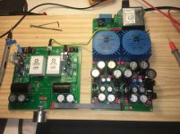
I have already assembled the Yarra / Hakuin components. The truth is that it is a fun project with a lot of documentation🙂. I am trying to make the voltage adjustment on the PS but I don't quite understand it ... I have used Talema 22v and I am measuring on the 2K2 resistors:
R155 = 31.7v
R156 = 33.2v
R175 = 31.9v
R176 = 33.2v
A121 Hakuin = 29.9v
A131 Hakuin = 27.3v
I don't understand why I can't regulate (lower) the tension in R156 / 176 which are the highest ... what am I doing wrong?
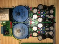


The cap Mx adjustment pot was not meant to be used to change the output voltage but rather the depth of the ripple reduction. The voltage drop you have may be from one Hakuin drawing a lot more bias current than the other. What are your currents across the output stage?
Thanks X for your answer, as always. I think I'm beginning to understand ...
Hakuin A-121 = 73ma
A-131 = 82ma
In the latter, the radiator of the 2SA1837 is also heated more.
Hakuin A-121 = 73ma
A-131 = 82ma
In the latter, the radiator of the 2SA1837 is also heated more.
This can be fixed by using matched JFETs or two from consecutive spots on a tape strip. Or don’t worry about it. :
As long as gain on both channels is close.
As long as gain on both channels is close.
The truth is that I asked for 2Sk170bl with Idss 7th or the closest ... that rage!
Isn't that much of an 11ma difference? can it be corrected from the same circuit?
Isn't that much of an 11ma difference? can it be corrected from the same circuit?
Last edited:
Hello,
I have already assembled the Yarra / Hakuin components. The truth is that it is a fun project with a lot of documentation🙂. I am trying to make the voltage adjustment on the PS but I don't quite understand it ... I have used Talema 22v and I am measuring on the 2K2 resistors:
R155 = 31.7v
R156 = 33.2v
R175 = 31.9v
R176 = 33.2v
A121 Hakuin = 29.9v
A131 Hakuin = 27.3v
I don't understand why I can't regulate (lower) the tension in R156 / 176 which are the highest ... what am I doing wrong?
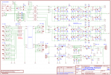
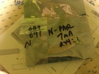
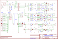
View attachment 997992
View attachment 997993
View attachment 997994
View attachment 997995
Your Yarra PSU is working perfectly, R155 /R175 represent the positive rails for each channel and are loaded down by the Hakuin boards. R156 / R176 represent the negative rails and remain unloaded, hence the slightly higher voltage. Use the Yarra positive rail trimpots to get voltage close between channels (there is <1v range). Do not use the Yarra psu to lower the voltage for the Hakuins, adjust the R's in the CRCRC on the Hakuin board to decrease the voltage. Hakuin's run at +24V.
- Home
- Group Buys
- The YARRA Preamplifier/HPA for Melbourne DB Group Buy
