I am one of those crazies who might build this thing. I already have a stash of larger SITs and some chokes in the proper range. I like seeing provisions for a bias supply that may be necessary with some devices. The extra cap in parallel with the output coupling caps is also a nice addition.
The most basic circuit could certainly be wired point-to-point, but the extra features are so much easier to build on a PCB.
The most basic circuit could certainly be wired point-to-point, but the extra features are so much easier to build on a PCB.
You're welcome.
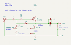
I am wondering whether it makes a difference whether that bias voltage is applied after R1 as you have done or before R1 as I have seen on schematics. It would be an easy change - locate the bias voltage connection where you show R1 and move R1 to be in series with the bias voltage connection. Jumper the bias voltage connection if it is not used.
The reason I thought a universal follower board would be good is because it seems to me that the majority of diyAudio members will only build an amplifier if boards are available. With a universal board, a builder could choose from a variety of Tokins and N channel VFETS, and various loads. It would be a Follower L'Amp.")
Good point Ben, while circuits like this are not difficult to p2p, I am more willing to choose a pcb option.
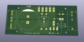
Alright, I've incorporated Ben's changes. Since the goal was to be a bit more universal, I called this version CYOF (Choose Your Own Follower).
- added over-voltage zener
- added external bias connection in series with R1
- added spot for a jumper when using self-bias
- Simplified R3/R4 connection in schematic and added another power resistor footprint (also makes for convenient point for jumper on external bias, or other arrangements).
- Annotated schematic to outline necessary changes for 'self-bias' or 'external bias'
Attachments
It should work. Looking at the curves here:
https://www.diyaudio.com/community/threads/tokin-sit-low-voltage-high-current-curves.346518/
It looks in the same range as the 2sk2087C. Might need to play with resistor values to adjust the bias, but it is in the range.
https://www.diyaudio.com/community/threads/tokin-sit-low-voltage-high-current-curves.346518/
It looks in the same range as the 2sk2087C. Might need to play with resistor values to adjust the bias, but it is in the range.
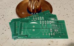
Another TDV is born! Wrapped up my little test build this afternoon. The boards worked great and fit the UMS pattern correctly. I got lucky with my K2087's, as they both landed at 1A4 using 1.1R for self bias. My secondaries are 22V, so I end up with 27.5Vdc rails once loaded. Dissipating just under 40W per device; my sinks are beefy, so heat is very reasonable (barely warm to touch). Iq was 1A38 when cold and 1A44 after an hour cooking.
I've been having issues with my Focusrite, so can't provide measurements quite yet. That said, I'm not sure I even want to bother – it sounds fantastic! I may play with a bit more bias at some point, but for now I'm enjoying things just as ra7 has prescribed. Sounds spooky with my little buffer>AVC>Edcor 1:5 setup and sounds rich and tubey with my Broskie SRPP pre.
Thanks again to ra7 for sharing his creation!!
Attachments
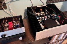
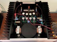
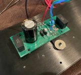
Thanks Vunce! The transformer is a 400VA 22V Antek. I swap things in and out of this chassis semi-regularly, so wanted something that could handle a variety.
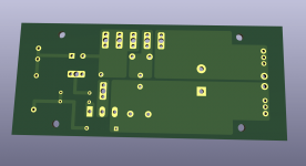
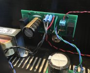
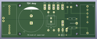
Speaking of ordering boards, I made a few minor tweaks to the TDV board recently. Nothing to do with the actual circuit, more of just niceties.
Absolutely nothing that will have any impact on performance. I don't want to flood this thread with another variant, but if anybody wants the gerbers let me know.
Speaking of ordering boards, I made a few minor tweaks to the TDV board recently. Nothing to do with the actual circuit, more of just niceties.
- slightly wider board to accommodate 37.5 film caps
- raised input connections to top of board
- subtle copper tweaks
Absolutely nothing that will have any impact on performance. I don't want to flood this thread with another variant, but if anybody wants the gerbers let me know.
Attachments
HI Codyt,what 2r2 black resistor are ? tnxAnother TDV is born! Wrapped up my little test build this afternoon. The boards worked great and fit the UMS pattern correctly. I got lucky with my K2087's, as they both landed at 1A4 using 1.1R for self bias. My secondaries are 22V, so I end up with 27.5Vdc rails once loaded. Dissipating just under 40W per device; my sinks are beefy, so heat is very reasonable (barely warm to touch). Iq was 1A38 when cold and 1A44 after an hour cooking.
I've been having issues with my Focusrite, so can't provide measurements quite yet. That said, I'm not sure I even want to bother – it sounds fantastic! I may play with a bit more bias at some point, but for now I'm enjoying things just as ra7 has prescribed. Sounds spooky with my little buffer>AVC>Edcor 1:5 setup and sounds rich and tubey with my Broskie SRPP pre.
Thanks again to ra7 for sharing his creation!!


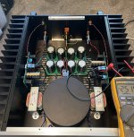
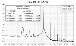
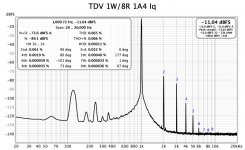
I got my Focusrite working again, so took some measurements. Interestingly, distortion rose when I went up to 1A7, though higher order stuff dropped some. Also, I think some of the PSU noise could be due to choke placement in my chassis.
The heat corresponds with my Iq measurements, but I did second guess myself that I'm actually measuring Iq correctly. I'm taking the voltage drop across (R3+choke) divided by the total resistance (R3+choke)... that sound right?
The heat corresponds with my Iq measurements, but I did second guess myself that I'm actually measuring Iq correctly. I'm taking the voltage drop across (R3+choke) divided by the total resistance (R3+choke)... that sound right?
Attachments
I would just measure Iq by the voltage drop across R3 since the DC resistance of the choke will increase as its warming up.
In my MoFo I had added a 0.1 ohm, 1%, 3W resistor in series with the drain of the output device. That way you can measure Iq whenever and the voltage drop across 0.1 ohm is minimal. I will add that extra 0.1 ohm when I build the amp.
Eric
In my MoFo I had added a 0.1 ohm, 1%, 3W resistor in series with the drain of the output device. That way you can measure Iq whenever and the voltage drop across 0.1 ohm is minimal. I will add that extra 0.1 ohm when I build the amp.
Eric
Would be interested in a pair of PCBs Vunce if you are going ahead to print and shipped to IL.Nice job Cody!
Whats the VA rating of the trafo? I’ll be joining in the fun soon, the files are in my next pcb order. I’ll have extras if anyone stateside is interested.
Thanks
- Home
- Amplifiers
- Pass Labs
- Total Domination VFET (TDV) Amp (using 2SK2087C)