Say no morejust chill
buggers are tough
with 60W of heat you can use cardboard as isolator pad, and they'll endure, until wire is melting-desoldered from source
and then again
 That's all the evidence I need.
Yup, that is it. Thanks for posting, Eric! The heatsinks are from Conrad Heatsinks (https://www.conradheatsinks.com/welcome.htm). I got them back in 2008 when I was just getting into this hobby. I bought a quad of them. They are superb quality. The 2U version was intended for a 10W JLH, which was never built. Instead, the love affair with Nelson began  . I also have the 4U version, which I have brought out for the SCG power amp. They need to be tapped.
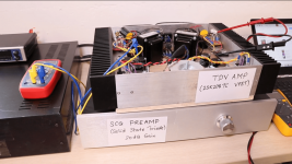
I can crank it to about 1.8 amps to get the TDV heatsinks screaming hot. The Tokin parts can be pushed to much higher bias, but about 8W is all I need at home. Originally had the Sony parts in there at about 1.6 amps. Easy-peasy for those sinks.
. I also have the 4U version, which I have brought out for the SCG power amp. They need to be tapped.I can crank it to about 1.8 amps to get the TDV heatsinks screaming hot. The Tokin parts can be pushed to much higher bias, but about 8W is all I need at home. Originally had the Sony parts in there at about 1.6 amps. Easy-peasy for those sinks.
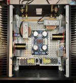
Build is coming together In a mini Dissipante 3U 300.
I goofed when ordering the film caps and got 30x30mm bricks. Also my 2087Cs are a bit low on the heatsink, but I’m pushing forward with that.
I’d like to ask: is there anything glaringly off with this layout? Would it be Ok to arrange the inductors symmetrically at the back?
I goofed when ordering the film caps and got 30x30mm bricks.
Also my 2087Cs are a bit low on the heatsink, but I’m pushing forward with that.I’d like to ask: is there anything glaringly off with this layout? Would it be Ok to arrange the inductors symmetrically at the back?
Attachments
Hi Marc
Nice work, very encouraging.
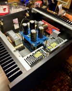
Are these 2 small switching mode power supply (SMPS) ?
If so, have you had a chance to verify if your SMPS can handle such a big CRC filters ? Some SMPS go into hiccup mode and can’t start normally (it keeps trying) if the equivalent resistance from these capacitors is too low.
Nicely done, just try to keep your amplifier pcb as far as possible from your SMPS and AC mains.
It’s nice to see another one of these being built 👍
Rgds
Eric
Nice work, very encouraging.
Are these 2 small switching mode power supply (SMPS) ?
If so, have you had a chance to verify if your SMPS can handle such a big CRC filters ? Some SMPS go into hiccup mode and can’t start normally (it keeps trying) if the equivalent resistance from these capacitors is too low.
Nicely done, just try to keep your amplifier pcb as far as possible from your SMPS and AC mains.
It’s nice to see another one of these being built 👍
Rgds
Eric
Last edited:
Thanks, Eric. Yes, I tested these SMPS with the cap boards shown a while ago as I was gathering things for a LuFo build. They powered up fine with no issues. That power supply got repurposed for this far simpler build.
https://www.diyaudio.com/community/threads/lufo-amp-39w-se-class-a-from-28v-rail.372679/post-7082254
If I’m lucky, this TDV will be powered up tomorrow for testing!
https://www.diyaudio.com/community/threads/lufo-amp-39w-se-class-a-from-28v-rail.372679/post-7082254
If I’m lucky, this TDV will be powered up tomorrow for testing!
Great point Eric, I was going to mention that also. A capMx with its slow start could be an option if the CRC is an issue for the SMPS's.
Looking good so far Marc!

Looks like my slow messaging missed your answer, LOL. Great news the supply is verified to work already
Looking good so far Marc!
Looks like my slow messaging missed your answer, LOL. Great news the supply is verified to work already
These SMPS are MeanWell RPS-200-27-C. 200 watt, +27 VDC output (adjustable).
https://www.digikey.com/en/products/detail/mean-well-usa-inc/RPS-200-27-C/7706042?
Well regarded in the big Modulus-86 thread. Worked fine with the diyAudio Store power supply boards.
https://www.digikey.com/en/products/detail/mean-well-usa-inc/RPS-200-27-C/7706042?
Well regarded in the big Modulus-86 thread. Worked fine with the diyAudio Store power supply boards.
Looking good! FWIW, I tried the choke’s in both front and back positions and noticed only a slight reduction in noise when keeping them further from transformer. That said, I’m not sure how/if they’ll interact much with the SMPS’.
Regarding that TO-220 (I think) resistor at R3 - pay attention to how hot it gets. I know that some of those larger package resistors state big dissipation, but it usually depends on heat sinking them.
For instance, I checked some TO-247 Reidon resistors I have. They're rated at 30W (when sinked) and 3W (free air).
Last edited:


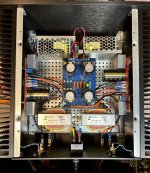
First power on is a success! Woo hoo!
Now, what’s the easiest way to check the bias?
27.8 VDC going to the boards. 1mV DC offset. Sinks getting warm, maybe ~45C. 1.1 and 1.2 VDC going to the inductors.
R3 is really hard to get to.
Now, what’s the easiest way to check the bias?
27.8 VDC going to the boards. 1mV DC offset. Sinks getting warm, maybe ~45C. 1.1 and 1.2 VDC going to the inductors.
R3 is really hard to get to.
Attachments
- Home
- Amplifiers
- Pass Labs
- Total Domination VFET (TDV) Amp (using 2SK2087C)