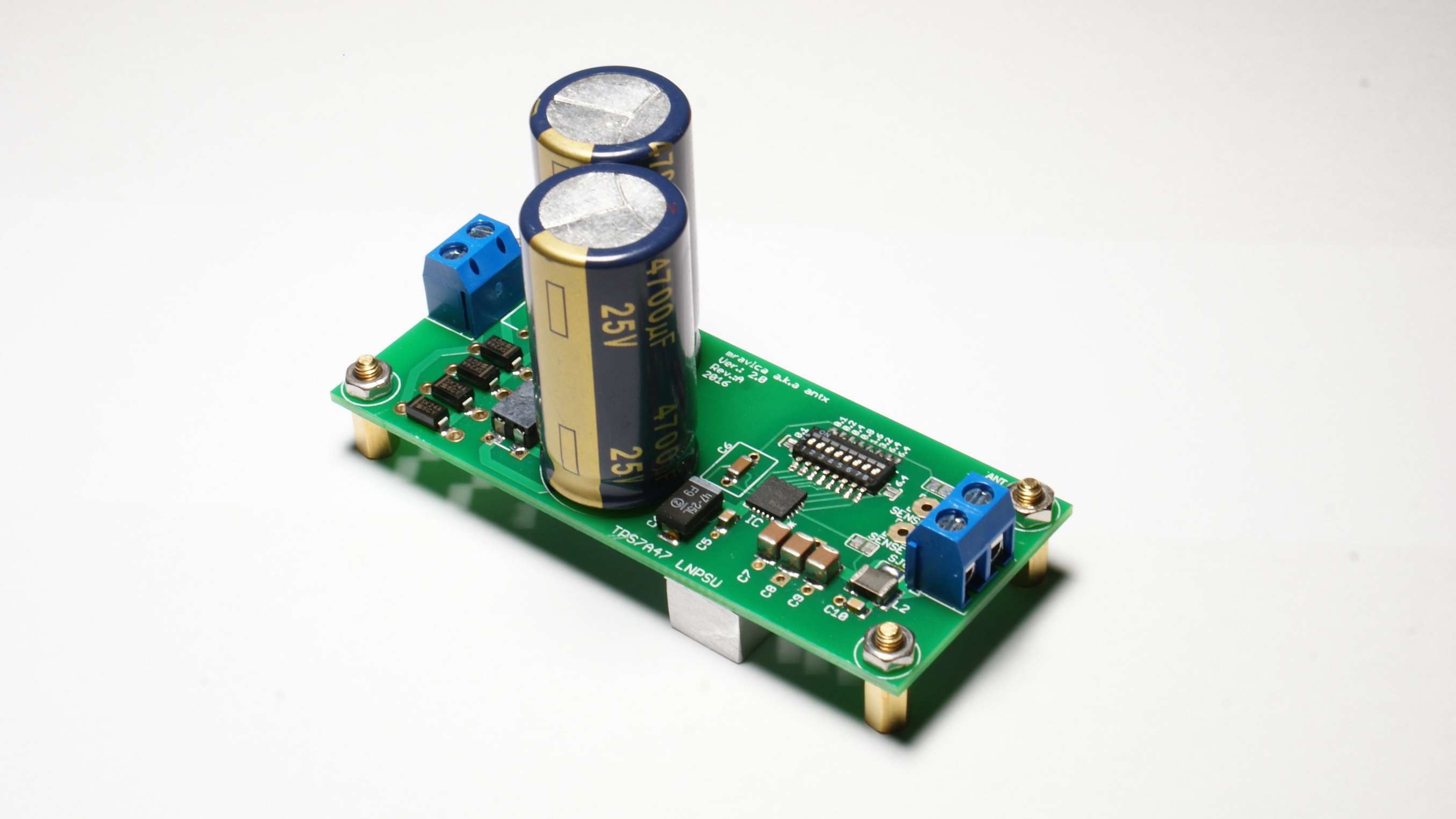
After long delay here is new TPS7A4700 PCB.
...
Hi and sorry to jump in with some questions maybe already answered.
I have seen on ebay some screenshots about the noise up to 100kHz.
I wonder if the noise above that could have an impact when the power supply is used with a dac, I mean the noise in the MHz region.
Do you have any other measurements screenshots ?
I need 12V/1A as clean as possible to power a dac.
Thanks a lot indeed.
Kind regards, gino
Hi Gino,
sorry but I don't have nay measurements above 100kHz, because that kind of equipment is really expensive... Though I can tell that I received some really positive feedbacks for various users who used this PSU to power thier DACs...
Best Regards,
Aleš
ps. 1A output is absolute maximum!
Ti made measurement ....at 1mhz is arround 0.01uV so very small. Every regulator in your dac has more noise. So if you want to do hi-end low noise regulation you should use mini Tps××× regs from Aleš on all lines....or at least in most important lines. Btw about which dac we are talking about? MF?
Hi Gino,
sorry but I don't have nay measurements above 100kHz, because that kind of equipment is really expensive...
Though I can tell that I received some really positive feedbacks for various users who used this PSU to power thier DACs...
Best Regards,
Aleš
ps. 1A output is absolute maximum!
Hi Ales, thanks a lot for the kind and valuable reply.
I have asked out of curiosity because i read some discussions on high Hz noise possibly impacting on dacs sound.
Great regulator you have designed/built indeed !
Kindest regards, gino
Ti made measurement ....at 1mhz is arround 0.01uV so very small. Every regulator in your dac has more noise.
So if you want to do hi-end low noise regulation you should use mini Tps××× regs from Aleš on all lines.... or at least in most important lines
Hi and thanks a lot for the very interesting info.
For sure this is an unbelievably low level of noise

I have just one power input on the circuit board actually.
Btw about which dac we are talking about? MF?
Well it is a commercial usb soundcard, not diy.
People have measured some spikes in the noise and the guilty happens to be the original smps.
Some people have decided to live with that saying that is low in level.
Others have replaced the smps.
I am thinking about replacing it trying to avoid to destroy anything.
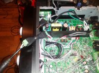
I have seen a current draw of about 450 mA at 12VDC for the circuit board.
I am attaching a picture of the unit under testing.
Thanks again and kind regards, gino
Attachments
Last edited:
Hi. MF is commercial dac ...Musical Fidelity.
That i was talking about...after big smps you have some more small smps regulators around pcb....they destroy excellent performance of Tps reg. Take scope and measure and you will see. Problems with smps is also huge gnd polutting with noise.
That i was talking about...after big smps you have some more small smps regulators around pcb....they destroy excellent performance of Tps reg. Take scope and measure and you will see. Problems with smps is also huge gnd polutting with noise.
Hi. MF is commercial dac ...Musical Fidelity.
That i was talking about...after big smps you have some more small smps regulators around pcb....they destroy excellent performance of Tps reg.
Take scope and measure and you will see.
Problems with smps is also huge gnd polutting with noise
Hi ! yes I see your point.
However I am trying to get to the best performance that this unit can provide.
My thinking is that supplying it with the cleanest 12VDC possible is the way to reach this limit.
In this way I could be sure that the power supply is not the problem for not excellent results.
I am testing different psu and for now the results are quite similar aside some bad cases. But I am still in the testing phase.
But I understand your point. It is a very common solution these days for usb soundcard, even good ones.
They have DC to DC converters on board to generate all the different voltages necessary for the various chips.
Thanks a lot again, gino
Last edited:
Yes first connect Tpsxxx from Ales then go on if you want do something more change this 3..4.. regulators this is 2hours job. Maybe check if regs have enable disable pin or function to not have problems with startup or similar reset functions... almost all Ldo regulators have on off pin. And carefull...some have max input of 5.5v...with Mravlcax regs...no problem with that.
New Board Size
Are the new TPS7A4700 PCB boards the same size as the old ones? If not, do you have layout templates for the new boards?
Cheers.
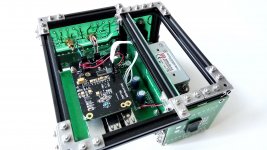
After long delay here is new TPS7A4700 PCB.
Are the new TPS7A4700 PCB boards the same size as the old ones? If not, do you have layout templates for the new boards?
Cheers.
Are the new TPS7A4700 PCB boards the same size as the old ones? If not, do you have layout templates for the new boards?
Cheers.
Hi Bryce,
new PCBs are a bit bigger. In the attachment there is new mounting plan.
Best regards,
Aleš
Attachments
Hi there.
1.
I'm wondering if I can hook up a 2xLiPoFe4=6,6-7,4V to generate clean 5V?
Is it recommended to bypass the diodes in this case?
2.
Further I am currently feeding a RPI with 5V from iFi iPower.
I am now considering to use two of your regs (3.3V) fed by the iPower
5V to supply clean voltage to a HAT DAC.
Is this working? or recommended?
Do you guys have better options in mind?
Thx.
Hi there.
1.
I'm wondering if I can hook up a 2xLiPoFe4=6,6-7,4V to generate clean 5V?
Is it recommended to bypass the diodes in this case?
2.
Further I am currently feeding a RPI with 5V from iFi iPower.
I am now considering to use two of your regs (3.3V) fed by the iPower
5V to supply clean voltage to a HAT DAC.
Is this working? or recommended?
Do you guys have better options in mind?
Thx.
Hi!
1. Yes this is possible. In order to supply PCB with DC voltage you can bypass diodes or solder wires after diodes. As you can see in this picture all diodes also have two vias.
2. It should work. But I really don't see any benefit in that. Ifi power supply already has low noise levels. Which model of Rpi are you using?
Option that I am currently using is TPS7A8300 regulator board that goes in between Rpi and DAC.
Best Regards,
Aleš
Attachments
Thx. Sounds good to me.
The iPower works really nice feeding the PI as primary DC source to feed the onboard regs.
I planned to keep it this way anyhow. It performs better than several linears I had at hand. The noise level is good. I agree. But the long cable is all but perfect. I attached a large capacitance right in front of the PI. That's been a nice improvement.
The HAT DAC (HifiBerry DAC+ Pro) requires at least 2*3.3V analog/digital.
These I'd like to cover.
Now I also have the new Mamboberry Lite in front of me . That requires 5V DC.
My plan is to use the iPower or your REG fed by two LiPoFe4s.
I'm running the PI2. No PI3? The PI3 is drawing more current. The drivers are not stable yet.
Onboard BT and Wlan sucks.
I was a little confused with the voltage settings until I looked them up in the datasheet @ page 14.
The voltages shown on the board might be a bit misleading.
I first thought I had to add them up. (For a reason though)
For my 5V application I ended up @ 400mV and 3.2V closed only.
Which obviously don't add up to 5V.
RTFM!
Oh no that would be a big mistake. At least reading Ales manual:
It says:
And that's wrong!
Ales Picture1 shows the correct config though!!!!
Ales, you might want to get this fixed!!
The voltages shown on the board might be a bit misleading.
I first thought I had to add them up.
(For a reason though)For my 5V application I ended up @ 400mV and 3.2V closed only.
Which obviously don't add up to 5V.
RTFM!
Oh no that would be a big mistake. At least reading Ales manual:
It says:
5V= 1.4 + 3.2 + 0.4 (Picture 1)
And that's wrong!
Ales Picture1 shows the correct config though!!!!
Ales, you might want to get this fixed!!
I was a little confused with the voltage settings until I looked them up in the datasheet @ page 14.
The voltages shown on the board might be a bit misleading.
I first thought I had to add them up.
For my 5V application I ended up @ 400mV and 3.2V closed only.
Which obviously don't add up to 5V.
RTFM!
Oh no that would be a big mistake. At least reading Ales manual:
It says:
And that's wrong!
Ales Picture1 shows the correct config though!!!!
Ales, you might want to get this fixed!!
Don't forget this from the paragraph above Picture 1:
You must not forget for the reference voltage which is 1.4V.
So 5V = 1.4 reference voltage + 3.2 jumper + 0.4 jumper
Cheers.
As BryceJ says, the TPS7AA4700 has a reference voltage that is always applied so, to set the board up, subtract 1.4 from the required output voltage and solder the jumpers that add up to the remainder.
I guarantee that if you bridge the 3.2V and 0.4V jumpers you'll get 5V output (assuming you have the correct input voltage from your transformer of course).
I don't think the instructions need amending.
Ray
I guarantee that if you bridge the 3.2V and 0.4V jumpers you'll get 5V output (assuming you have the correct input voltage from your transformer of course).
I don't think the instructions need amending.
Ray
5V = 1.4 reference voltage + 3.2 jumper + 0.4 jumper
That's the missing link. He should change it this way to avoid confusion.
But even "reference voltage" doesn't say much.
I'd rather call it base/default voltage.
- Home
- Vendor's Bazaar
- TPS7A4700 low noise LDO regulator PCB