Of you want the best use a lipo or lifepo4 with the pcb from ales.I recently had a look at the noise statistics for various batteries. A NiCd battery came out on top. You would have imagined that a simple battery would be as clean as it comes.
I am planning on using twisted pair wires from a solid core CAT5 network cable to wire up my home brew Tentlabs XO oscillator and TPS7A4700 regulator combination. I am going to wind the twists more tightly which I am figuring will improve the immunity to any stray fields.
Hi Ales,
I have seen that Version 2.0 is now in Rev. B
Could, you please, tell us more about these changes.
Are there any other changes that those 2pcs of 3300uF/25V Panasonic FC instead the 2 pcs of 4700uF 25V Panasonic FC in the Rev. A ?
(and why this ?)
And what the changes and resons in this Revision ?
Thanks in advance and have a nice day.
PS
I cannot located the Ferrite bead Wuerth on the fotos of PCB, can someone enlighten this to me, thanks in advance
Last edited:
...
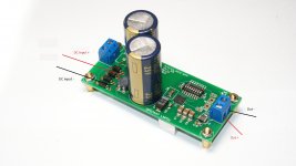
1. Yes this is possible. In order to supply PCB with DC voltage you can bypass diodes or solder wires after diodes. As you can see in this picture all diodes also have two vias.
...
Hi Ales,
Could you please, show me exactly the place where one can solder the wires in order to connect the DC voltage ? (I have the version 2.0 Rev A)
Thanks in advance and have a nice day.
Last edited:
Hi Ales,
Could you please, show me exactly the place where one can solder the wires in order to connect the DC voltage ? (I have the version 2.0 Rev A)
Thanks in advance and have a nice day.
Hi Dziki,
Please see the image attached. Hope that helps.
Best Regards,
Aleš
Attachments
Last edited:
Version 2, Rev. B
Version 2 Rev. B has been around a while but I haven't really made any notice about it.
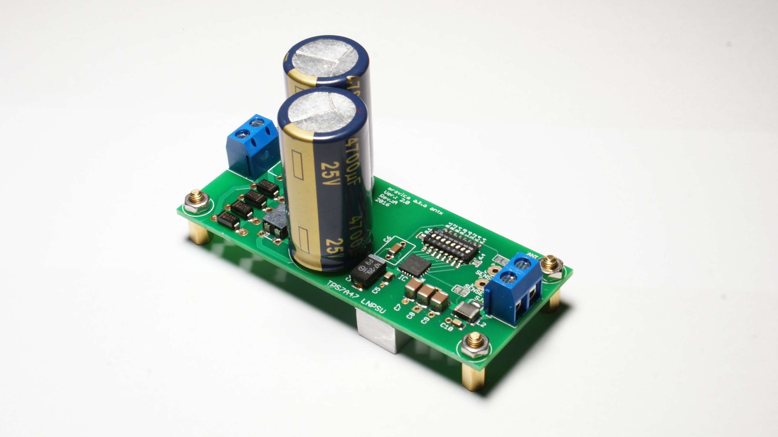
From Rev. A it first differs in size. Rev B measures 67mm x 35mm. Through hole capacitor in the feedback loop was removed and now there is 1uF X7R in parallel with 100nF N0P. Then there are markings for inputs and outputs, also DC input has separate holes to avoid going through diodes. Setting output voltage is also much more easier as all Rev B PCBs are equipped with SMD dip switch, (no more tricky soldering to configure output voltage). Output ferrite is rated at 3A to avoid saturation in any case. If someone is concerned about output impedance of the regulator with ferrite bead it can easily avoided with soldering solder jumper SJO. However I still advise to use kelvin sensing for best performance. When kelvin sensing is used SJO MUST be shorted, otherwise regulator will oscillate as there will be "coil" in the feedback loop.
BTW price for one PCB is 26.5€.
Version 2 Rev. B has been around a while but I haven't really made any notice about it.
From Rev. A it first differs in size. Rev B measures 67mm x 35mm. Through hole capacitor in the feedback loop was removed and now there is 1uF X7R in parallel with 100nF N0P. Then there are markings for inputs and outputs, also DC input has separate holes to avoid going through diodes. Setting output voltage is also much more easier as all Rev B PCBs are equipped with SMD dip switch, (no more tricky soldering to configure output voltage). Output ferrite is rated at 3A to avoid saturation in any case. If someone is concerned about output impedance of the regulator with ferrite bead it can easily avoided with soldering solder jumper SJO. However I still advise to use kelvin sensing for best performance. When kelvin sensing is used SJO MUST be shorted, otherwise regulator will oscillate as there will be "coil" in the feedback loop.
BTW price for one PCB is 26.5€.
Attachments
...
However I still advise to use kelvin sensing for best performance;
...
Thanks Ales for your reply.
Is the use of Kelvin sensing suitable for any loads ?
Yep, kelvin sensing is the way to go. A lot of folks find it hard to implement, but it is just two extra wires really. Check more here: https://en.wikipedia.org/wiki/Four-terminal_sensing
Regards,
Aleš
Regards,
Aleš

View attachment 590015
The connection should be like this ? (picture attached)
Just two wires together for each ("+" & "-") ?
That's it. But make sure you connect wires as close as possible to the load.
...
But make sure you connect wires as close as possible to the load.
You mean the load (powered device) must be as close as possible to the regulator (your PCB) ?
or ?
That is also very desirable, but it is not what I meant. What I was trying to say is you connect wires on the connector of powered device (not somewhere in the middle)...You mean the load (powered device) must be as close as possible to the regulator (your PCB) ?
or ?
")
- Home
- Vendor's Bazaar
- TPS7A4700 low noise LDO regulator PCB