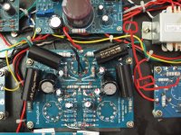
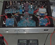
Today I received my amp but unfortunately it came with a lot of damage, the top plate was crushed by the weight of the transformers.
The transformers were almost torn, and inside the large capacitors are pushing the bottom plate.
The weirdest part is that the shipping box has no damage.
The only positive part is that despite so much damage amplifier works well and the first hearings show that has potential.
Now I do not know what to do.
I Can return the amp, bear the cost of transport and run the risk of receiving an even worse one, or I can try to fix this one but it seems to be a difficult job.
I can also try to make a new box (more beautiful) but this is even an harder work living in a small studio with few tools. (I still remember how much I sweated building my open baffel).
Anyone has suggestions or advice please?
Attachments
I contacted the seller of the amplifier and he asked me if I could accept a new box. I accepted because I am not willing to send the amplifier back to China at the risk of receiving an amplifier that can come back even in worst condition.
I know I will have to work hard and need a lot of patience to change the amp from one box to another.
I am also thinking that I can simplify things removing everything that I don't need such as USB, Phone and MP3.
Either way I will need all the help that members of the forum can give me, I'll post pictures and would like to receive feedback and suggestions.
Today I was off and I decided to change the capacitors, the amplifier still works and the improvement in sound is huge . (I'm starting to feel happier, this may turn out to be a good opportunity to learn).
Now I'm looking at the list of modifications of the post No. 81 made by Globulator, and the “general part” is completed.
On the part of “Input section (6N3s)” I have doubts, can I make changes in this part without changing anything in the “Driver section (6N1)” and in the connections of the transformer, or are these changes linked to each other?
If I can change the "Input section (6N3s)", would anyone please post a picture of that section with the resistors, capacitors and FB components marked (I would not want to remove the wrong parts).
Cheers,
Attachments
Hi!
Been on holiday - getting back into the swing of things. The Amp still sounds as awesome as I remember it, which is good!
1) The 6N3 input stage is independent of the other stages - go ahead and change!
2) The 6N1 to 6N6 or ECC82 stage is independent too!! I suspect a 6n6p will sound just as good as an ECC82 if you do not want to rewire the PCB, but you will need to use a different bias resistor (and feedback resistor for the #81 Hot Sugar mod).
3) Moving the feedback wires from the 6N3 stage to the ECC82 stage inverts the feedback, which is why you need to flip the transformer wires if you do this. This feedback relocation/transformer flip is connected!!
Sorry you got a bent box. The amp is not too difficult to rebuild and the power transformer is 'potted' so of good quality, haven't opened the others. When you dismantle the box _please_ ensure the HT wires are discharged fully, the main PSU board supplied 430Vdc via the red wires (and transformer primary) to the red wire on the FU50 boards. I find waiting 1min and then connecting a 2.2k (about) resistor from the FU50 red wire to ground for 1min is the safest way to get the voltages out.
While you rebuild the box you may wish to put an ALPs motorised pot in, there is a small one on eBay I bought (100k log) 100KDX2 which should fit OK, I have not fitted it yet though. I also need the remote controller..
Been on holiday - getting back into the swing of things
. The Amp still sounds as awesome as I remember it, which is good!1) The 6N3 input stage is independent of the other stages - go ahead and change!
2) The 6N1 to 6N6 or ECC82 stage is independent too!! I suspect a 6n6p will sound just as good as an ECC82 if you do not want to rewire the PCB, but you will need to use a different bias resistor (and feedback resistor for the #81 Hot Sugar mod).
3) Moving the feedback wires from the 6N3 stage to the ECC82 stage inverts the feedback, which is why you need to flip the transformer wires if you do this. This feedback relocation/transformer flip is connected!!
Sorry you got a bent box. The amp is not too difficult to rebuild and the power transformer is 'potted' so of good quality, haven't opened the others. When you dismantle the box _please_ ensure the HT wires are discharged fully, the main PSU board supplied 430Vdc via the red wires (and transformer primary) to the red wire on the FU50 boards. I find waiting 1min and then connecting a 2.2k (about) resistor from the FU50 red wire to ground for 1min is the safest way to get the voltages out.
While you rebuild the box you may wish to put an ALPs motorised pot in, there is a small one on eBay I bought (100k log) 100KDX2 which should fit OK, I have not fitted it yet though. I also need the remote controller..
Thanks Globulator,
I hope your holidays have been good.
I would like to make a complete change for the “Hot Sugar mod”, I'll make changes step by step and I'd like you to check please if I'm not messing up.
Changes to 6N3 input stage:
Optional - remove all FB components:
Changes in Driver section (6N1 to ECC82):
At this point I start to have a lot of problems, there are a series of links that I can not figure out.
Rewire for parallel filaments:
Transformers (Swap the wires around) :
List of stuff to buy:
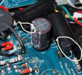
Since I will rebuild the amp completely, I would appreciate any suggestions you have for the replacement of components by others of better quality, for example, I'm thinking that I can also replace the two big brown capacitors that seems to have suffered impact during the transport.
I would like to thank you again for the help and time spent to support a beginner in DIY
Cheers,
I hope your holidays have been good.
I would like to make a complete change for the “Hot Sugar mod”, I'll make changes step by step and I'd like you to check please if I'm not messing up.
Changes to 6N3 input stage:
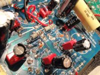
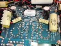
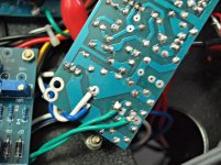
- Repalacing 1R5 and 2R5 by two 2.2 k resistors - (nr. 1 in picture)
- Remove the 220u cathode bypass caps 1C2 and 2C2 – (nr. 2 in picture)
- Unsolder the FB wires and free from the tyraps 1F and 2F - (nr. 3 in picture)
Optional - remove all FB components:
- Caps 1C6 and 2C6, - (nr. 4 in picture)
- Can I remove also Caps 1C5 and 2C5 ? - (nr. 5 in picture)
- Resistors 1R6 and 2R6 – (nr. 6 in picture)
- Can I remove also Resistors 1R3 and 2R3 ? – (nr. 7 in picture)
- Big Cap, should I remove this one to? - (nr. 8 in picture)
Changes in Driver section (6N1 to ECC82):
At this point I start to have a lot of problems, there are a series of links that I can not figure out.
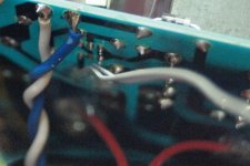
Rewire for parallel filaments:
- Loking to your picture I think I should move the black wire from position B to C, a Make new link from position C to D, I also should connect the A position to B.
- I can not figure out what is the track that I should cut, please can you post a picture with the track that I should cut?
- Adding an NTC thermistor, Can you tell me please what thermistor should I buy? How should I connect it to the ECC82?
- Replace the 1k cathode resistors for 1.5k, Is it the nr. 9 in picture?
- Remove the 220u cathode bypass caps, Is it the nr. 10 in picture?
- Change the negative feedback, if I understand it, I must connect 5.6k resistor from the FU50 grid to the feedback wires.- (E and F in picture).
Transformers (Swap the wires around) :
- In this photo you can not see the wire connection to B+ but I think it should be at the back of the circuit board near the H position, I also think that the red wire that connects the Transformer to the FU50 is the indicated at position G, am I right?
List of stuff to buy:
- Two 2.2 k resistors (how many wats? any recommendations regarding the type or brand?)
- Two 1.5 k resistors (how many wats? any recommendations regarding the type or brand?)
- Two 5,6 k resistors (how many wats? any recommendations regarding the type or brand?)
- One NTC thermistor (I have no idea what to buy)
- One ECC82
Since I will rebuild the amp completely, I would appreciate any suggestions you have for the replacement of components by others of better quality, for example, I'm thinking that I can also replace the two big brown capacitors that seems to have suffered impact during the transport.
I would like to thank you again for the help and time spent to support a beginner in DIY
Cheers,
Attachments
Last edited:
Ok - some more careful reading of #81 required I think!
Based on your first picture this is the change list, based on the red letters. I describe one channel - obviously the other channel needs doing the same.
Starting point (remove bypass and feedback caps)
Remove caps 2, 4 and 10
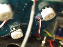
ECC82 filament mod (not needed for 6n6p):
Cut track from B to D, and move wire from B to D
Bridge A and B
Connect a new wire from D to C (I added NTC here)
- no idea what type of thermistor as I got it from a broken SMPS
- you could try a 1 or 2ohm resistor to start
ECC82 bias
Replace res 9 with 1.5K
- 0.6W metal film will be fine
DN3 bias
Replace res 1 with 2.2K
- 0.6W metal film will be fine
Feedback
Unsolder feedback wires at 3 and wire to top of res 9 (ECC82 cathode) via a 5.6K res
- I did this from the top, no need to remove board
- red and white are in parallel (connected together)
- This bit is difficult to do in a tidy way
Invert transformer primaries (beware electric shock!)
- this means swap the red OPT wires between B+1 on the PSU PCB to G on the FU50 PCB
(OPT = output transformer, the red wires go to the primary and connect the power into the big FU50 output tubes.)
Based on your first picture this is the change list, based on the red letters. I describe one channel - obviously the other channel needs doing the same.
Starting point (remove bypass and feedback caps)
Remove caps 2, 4 and 10
ECC82 filament mod (not needed for 6n6p):
Cut track from B to D, and move wire from B to D
Bridge A and B
Connect a new wire from D to C (I added NTC here)
- no idea what type of thermistor as I got it from a broken SMPS
- you could try a 1 or 2ohm resistor to start
ECC82 bias
Replace res 9 with 1.5K
- 0.6W metal film will be fine
DN3 bias
Replace res 1 with 2.2K
- 0.6W metal film will be fine
Feedback
Unsolder feedback wires at 3 and wire to top of res 9 (ECC82 cathode) via a 5.6K res
- I did this from the top, no need to remove board
- red and white are in parallel (connected together)
- This bit is difficult to do in a tidy way
Invert transformer primaries (beware electric shock!)
- this means swap the red OPT wires between B+1 on the PSU PCB to G on the FU50 PCB
(OPT = output transformer, the red wires go to the primary and connect the power into the big FU50 output tubes.)
Last edited:
Hello Globulator, thanks for the help,
I just returned from work, and if you do not mind I have some questions.
You said in your instructions to connect the feedback wires to the top of the resistor, please confirm whether the correct position corresponds to the red point in photo.
Initial searches on ebay and I only could find the 1W resistors, can I use those?
NTC thermistor the smallest I could find is 5 ohm, is it to much?
Cheers
Attachments
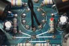
Any resistor of 0.5W or over will be fine for all the changes.
The red dot is the correct place (the tube cathode - check out the pinout of the ECC82) for the feedback mod.
Tube datasheets are your friend - Google for "ECC82 datasheet" to find them.
Do the other mods first and make sure the amp still works
Then discharge all voltages to zero
Then do the feedback mods.
ETA: Thermistors vary with temperature - you just have to try them out, it's just to stop the filament shock, try one and measure the voltage before and after - you are aiming for 6.3V. Don't worry about this bit too much until you get the rest working, if you are stuck try a 1ohm resistor instead.
Last edited:
When you rebuild you may want to just pop in a couple of tube bases and wire it point to point, you can also get rid of a 6N3p tube to save a bit of energy and heat!
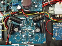
I took off all the spare components - ignore the big 1R resistor, I have 245Vac and need to lower the filament voltages!
I have also added a couple of bypass capacitors too, if I redesigned the layout I'd try to use non-electros instead, but I'd need to manage the space.
I took off all the spare components - ignore the big 1R resistor, I have 245Vac and need to lower the filament voltages!
I have also added a couple of bypass capacitors too, if I redesigned the layout I'd try to use non-electros instead, but I'd need to manage the space.
Attachments
Hello Globulator,
Your suggestion is very interesting and tempting, but I am a beginner and without having instructions on how to make the connections I do not even know where to start.
Either way is a subject on which I have to think seriously, because I have not received reply from the seller regarding the new box, I'll probably have to make myself a new one.
I'm still waiting for parts I ordered to make modifications to the amp and as I'm off tomorrow I will take the time to look for parts to make the box.
I really want to simplify the layout of the amplifier and if I can pull off a tube I think it would be another step in the right direction.
I do not need much power, 5w is more than enough for my speakers, and do not mind spending a little more in components to to have a good amplifier.
If you can consider to guide me in this project, I can assure you that I am very careful to follow directions when I do not know what to do, and I am well aware of the risks involved.
Thank you for your time and attention,
Alexandre
I am a beginner and without having instructions on how to make the connections I do not even know where to start.
The good thing about tubes, is that although they can result in some amazingly complicated and subtle circuits, they can also be very simple: and the Sweet Peach circuit is very simple too!
To make it simple for you too, you need to look up a few things:
Not sure how your electronics is, but you need to understand voltage, current, power, resistance and what capacitors do.
You need to read and understand this:
How to "Screw Around" Your Tube Load Line
first. Tubes basically conduct unless switched off. You switch them off with -ve grid voltage, which is why the load lines have -ve numbers, like -2V.
To get a negative voltage, you add a cathode resistor (the one at the bottom), so the cathode is at a +ve voltage so when you ground the grid you get a relative -ve grid voltage.
So now you have the anode resistor (the big one on top), the tube with the grid controlling it, and the cathode resistor. That's all this amp has really, although the output tubes have a special -ve bias (grid) supply because you need around -70V on there, which isn't going to be possible with a small cathode resistor!
A tube is a voltage in, current out device, which is why you can drive them with small capacitors. You also have a resistor connected straight to the grid first - check the schematic. This is a 'grid stopper', which damps any oscillation of the tube.
So in fact for the first stage of the Sweet Peach we have a very simple circuit, input comes from the input pot (volume control) via a 3k grid stopper resistor into the grid. The cathode is connected to ground via a 2.2k resistor. The anode is connected to 350V via a 100k resistor.
That's it really, there is a resistor and capacitor also involved in providing the 350V (its just a simple RC (Resistor/Capacitor) hum reduction stage).
So as long as you connect up the correct pin of the tube to the right components it all works
. To get the pinouts for the tubes and the load lines, just look them up on google to find the PDF with the data in it. For instance: 6n3p datasheet - Google SearchHave a good read and it will all become much simpler - as with anything stuff you do not know is difficult, stuff you do know is simple - I think it will only take you a week or two of study to know why each wire is connected as it is, which will be far better for you when rebuilding the Peach!
Hello Globulator,
Thanks for the help,
Yesterday I had a busy day, first went looking for materials and tools to make the case but the cost of the project began to make no sense (the tools are expensive), but as I got an email saying that the supplier would send me the case, I decided to set aside for now the idea of making connections point by point.
The rest of the day I spent it trying to figure out how to simplify the amp by removing the connections that I do not need.
In the end I ended up redoing the connections to just stick with the the AUX connected to the Volume Pot.
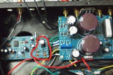
There is however a board I would like to remove but it seems to me that I can not.
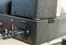
The board is that the left side of the power board, this board is connected to the power transformer by two green wires that after passing a set of four diodes and capacitors is connected back to the ACin3 on the Power board.
If I disconnect the green cables the amplifier stops working, and I think I can not connect those directly to ACin3, because the sets of diodes are converting AC to DC before send it back to Acin3. Can you please tell me if my reasoning is correct?
I have been looking at the bottom of power board and I'm expecting a very difficult work to redo the soldering when changing the new box (why they had to leave the wires short?)
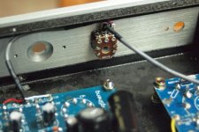
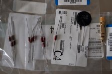
Today I received some parts, the thermistor is a monster in size and the resistances, while being of 0,5W are also big. (I'll have to think what will be the best way to fit these monsters).
Still waiting for tubes, thus the rest of the changes will have to wait a bit.
Cheers
Thanks for the help,
Yesterday I had a busy day, first went looking for materials and tools to make the case but the cost of the project began to make no sense (the tools are expensive
), but as I got an email saying that the supplier would send me the case, I decided to set aside for now the idea of making connections point by point.The rest of the day I spent it trying to figure out how to simplify the amp by removing the connections that I do not need.
In the end I ended up redoing the connections to just stick with the the AUX connected to the Volume Pot.
There is however a board I would like to remove but it seems to me that I can not.
The board is that the left side of the power board, this board is connected to the power transformer by two green wires that after passing a set of four diodes and capacitors is connected back to the ACin3 on the Power board.
If I disconnect the green cables the amplifier stops working, and I think I can not connect those directly to ACin3, because the sets of diodes are converting AC to DC before send it back to Acin3. Can you please tell me if my reasoning is correct?
I have been looking at the bottom of power board and I'm expecting a very difficult work to redo the soldering when changing the new box (why they had to leave the wires short?
)Today I received some parts, the thermistor is a monster in size
and the resistances, while being of 0,5W are also big. (I'll have to think what will be the best way to fit these monsters).Still waiting for tubes, thus the rest of the changes will have to wait a bit.
Cheers
Attachments
I'd wait for the case, or bend back the old one
Your photo with the pot is interesting, I will wire my driver circuit point to point later because I want to use an Alps motor pot there, but the driver board is in the way!
I quite like the selector actually!
That 12V (or so) comes from the MM phono board, and is used I think for the delayed HT switch on (soft start) via the relay. I tried to take that board out too and found out the same thing! I wired the phono MM input straight to the input pins - so that board on mine just sits there providing power to the soft-start relay.
I noticed the power wires were short too, not much space under there for longer ones either. There should not be too many wires from the transformer to the pcb though - 4?
Hello Globulator,
I have some good news, today I had time to make the "Hot Sugar mod".
Grid voltage on the ECC82 is 5.5/5.6 and on the 6N3 is 4.5/4.6(maybe a little high?).
The best part is that nothing is burned, I was not electrocuted, and the sound is really good, none of this would have been possible without your help, again thank you Globulator.
When I was doing the soldering I slightly melted the coating of some capacitors, will I'll have problems with this?
Unfortunately I have not yet received the box from the manufacturer and therefore can not finish the amp. I'll wait another few days and then have to solve the problem.
After a few hours playing my power transformer gets very hot (I can leave my hand on top for only a few seconds before becoming uncomfortable), the other transformers are just warm, do you think these temperatures are normal?
Can you tell me please what were the changes in the sound achieved with the addition of the last two bypass capacitors in post 112? Should I also consider those changes and the removal of other spare components?
Cheers,
I have some good news, today I had time to make the "Hot Sugar mod".
Grid voltage on the ECC82 is 5.5/5.6 and on the 6N3 is 4.5/4.6(maybe a little high?).
The best part is that nothing is burned, I was not electrocuted, and the sound is really good
, none of this would have been possible without your help, again thank you Globulator.When I was doing the soldering I slightly melted the coating of some capacitors, will I'll have problems with this?
Unfortunately I have not yet received the box from the manufacturer and therefore can not finish the amp
. I'll wait another few days and then have to solve the problem.After a few hours playing my power transformer gets very hot (I can leave my hand on top for only a few seconds before becoming uncomfortable), the other transformers are just warm, do you think these temperatures are normal?
Can you tell me please what were the changes in the sound achieved with the addition of the last two bypass capacitors in post 112? Should I also consider those changes and the removal of other spare components?
Cheers,
Attachments
Excellent!! Do you like the sound? It will vary depending upon your speakers a bit - but I think it has a good solid yet relaxed quality. The ECC82 is right in the middle of a nice linear region there - combined with degeneration it's probably the best they sound!
The caps look OK - if you are worried make sure the ones going to the output GU50 tubes are perfect - that's the tube you do not want turned fully on!
I find my power transformer gets warm too. It's a potted transformer so it should be OK, but you can reduce power by reducing the tube bias to 50mA or even 45mA. I think they should sound best at 55mA but I'm not sure, and you can raise them in the winter anyway - for the summer mine are at 52.5mA now and I run the amp only for 2-3 hours max.
So try 45mA (0.45V) and see how it sounds - if it's good enough (no clipping and sounding solid) leave it there for a cooler power transformer.
Your thermistor disc is huge - twice as big as mine!! Should be fine though, you only need about 6V at the filaments and not to see them 'glow' like a lightbulb when you switch on!
The capacitors across the B+1 and B+2 are there because I 'know' the electros need bypassing. I only had a 0.1u for the B+2 (I mounted that on the driver board) - not sure how much that does, there is a 5uF on the B+1 board, that is a motor start capacitor from an old central heating pump that died! I think that tied the sound together a little better but the effect will be subtle.
I'm planning another mod for this amp, which may involve a new top-plate and just 2 tubes being used - possibly with two glowing voltage regulator tubes - which should be fun. The idea is to move the feedback from speakers and just get it direct from the GU50 anode, at a higher FB level, and run the the GU50 as a pentode. This will force the ECC82 + GU50 into a very linear low impedance drive for the output transformers (OPTs) - effectively turning them into better transformers.
Hi,
The sound seems to already have won in detail, but I also exchanged tubes today so it is premature to reach conclusions.
I replaced the FU50 by GU50, but two tubes I bought do not seem to be good.
Cheking de bias, in one tube voltages jumped randomly to eventually rise to more than 10V, this resulted in some smoke out of the tube soket ... the other tube also showed random voltages and ended up with a purple color... so I bought four tubes and two went to the trash.
The other two tubes, showed a bias of 0.4, much lower than that of FU50, maybe the GU50 and FU50 are not exactly alike?
In the end I got the GU50 + 6N3-DR + Hytron audio 5814A runing in the amp whit a bias of 0.55,
but I will try also with 0.45.
I'll be looking at your next mods, because if do not receive the new box I'll probably have to
to rebuild everything from scratch an you mod could be very interesting.
Cheers
The sound seems to already have won in detail, but I also exchanged tubes today so it is premature to reach conclusions.
I replaced the FU50 by GU50, but two tubes I bought do not seem to be good.
Cheking de bias, in one tube voltages jumped randomly to eventually rise to more than 10V, this resulted in some smoke out of the tube soket
... the other tube also showed random voltages and ended up with a purple color... so I bought four tubes and two went to the trash.The other two tubes, showed a bias of 0.4, much lower than that of FU50, maybe the GU50 and FU50 are not exactly alike?
In the end I got the GU50 + 6N3-DR + Hytron audio 5814A runing in the amp whit a bias of 0.55,
but I will try also with 0.45.
I'll be looking at your next mods, because if do not receive the new box I'll probably have to
to rebuild everything from scratch an you mod could be very interesting.
Cheers
I replaced the FU50 by GU50, but two tubes I bought do not seem to be good.
Checking the bias, in one tube voltages jumped randomly to eventually rise to more than 10V, this resulted in some smoke out of the tube soket
I think the GU50 tubes have some gas in them that needs to be gently burnt off into the getter. One of mine (I only tried 2) had a purple glow too (that's the gas) but I had the amp on the variac at about 1/2 voltage so it could not do damage. After about 5 minutes the gas was gone and the getter (the coating at the top) had been used (white around the edges). The bias changed during this time.
I did not found the sound of the FU50 and GU50 to be different so maybe the FU50s are fine anyway!
You may want to heat the GU50 tubes in the oven at 120 degrees C for an hour to activate the getter and de-gas them.. when you try them use a lower voltage (have you a variac?) to check. Remember you need some voltage to switch the HT on - via the relay on the power PCB.
All tubes also settle in - you need to tweak the bias until the tubes are stable again as they will drift for a while as the getters work etc.
- Status
- This old topic is closed. If you want to reopen this topic, contact a moderator using the "Report Post" button.
- Home
- Amplifiers
- Tubes / Valves
- Trying to make sense of the Sweet Peach