If your chassis has enough height, you can mount the tranformers vertically to gain some floor space. If you don't mind the bolt heads visible on the outside of the case, you can mount the transformers directly to the side panel.
I just checked the dimensions of a 3U chassis and AS-3218 and it looks like it's close but no go.
I just checked the dimensions of a 3U chassis and AS-3218 and it looks like it's close but no go.
Thanks, Istvan!
I do not have a circuit diagram, and it would take me ages to draw one. 😆
I just followed peppenino’s build in his Aleph J, with:
I do not have a circuit diagram, and it would take me ages to draw one. 😆
I just followed peppenino’s build in his Aleph J, with:
- (2) AS-3218 toroids
- (4) Hammond 159ZJ inductors
- ZM’s cap bank boards and thermistor boards
- (4) 22mF 35V Caps per board
- Schurter fused IEC inlet/switch
Inching closer to power testing! 
I will make a temporary wooden rear panel first, then will order a cut aluminum one.
I’m going to pour over all my connections and associated logic before I fire it up with the dim bulb tester.
I will make a temporary wooden rear panel first, then will order a cut aluminum one.
I’m going to pour over all my connections and associated logic before I fire it up with the dim bulb tester.
Attachments
DBT power up was successful and uneventful! Similarly, power up without DBT was fine. +/- 24.4 VDC on the powercon outputs, unloaded. 15 and 13 mVAC on the outputs (don’t know yet if that’s a noise problem). No sparks, smoke, explosions, vibrations, or sound. I’m GIDDY. Can’t wait to try it with a Pass Amp. My idling F5 boards will likely be the first test. I’ll be swapping in some 2SK1530/2SJ201 to those… 
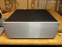
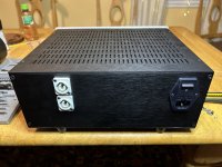
All buttoned up.
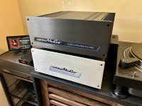
I doubled the top with an additional Galaxy baseplate for added strength, since I may put whatever power amp it is serving on top. This is one heavy piece. Maybe that’s what I’ll name it: OHP.
I doubled the top with an additional Galaxy baseplate for added strength, since I may put whatever power amp it is serving on top. This is one heavy piece. Maybe that’s what I’ll name it: OHP.
Attachments

Congrats, von Ah! You starting up your project finally prodded me to do the same, so thank you.
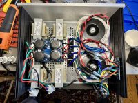
I also just finished my dual mono power chassis. I opted to use two powerCON umbilicals to supply the amp boards and a locking stereo ¼” jack to power the speaker protection board and provide the safety ground through the sleeve. Everything is functioning well. Pictures are below. Since I ripped this power supply out of my existing Aleph J build, I reused many of the wires, which is why it looks a little spaghetti-like.
In the amp chassis, as many of you suggested, I put in another set of caps. Currently, the only connection between the power supply’s ground and the chassis ground is through a pair of CL60s in the amp chassis, which was a suggestion someone made in another thread. If this grounding scheme doesn’t work, I’ll probably go with what Analogico laid out in his diagram with the ground lifts in both chassis.
Anyway, I wanted to show you all a complete setup with the amp chassis done and connected… but alas, a smokey smell arose from one (and thankfully only one) of the amp boards (it looks like R17, 25, and 26 got a little toasty), so I’m sure I’ll be making an appearance at the Aleph J thread soon. A pic of the amp chassis is also below.
 ), they give the opportunity to build and try countless amps
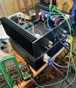
 I made it to the first test of powering an amp with the separate power supply. This includes:
Bias procedure will continue after dinner is sorted for me and my kids. ☺️
- Upgraded F5 boards with 2SK1530 / 2SJ201
- Spare 3U300 sinks
- Repurposed previous back panel from the power supply chassis
- Some brackets and makerbeams to maintain a solid box
- One 6’ 14AWGx3 IEC power cord sacrificed to make a couple DC powercon cables
Bias procedure will continue after dinner is sorted for me and my kids. ☺️
Attachments
Last edited:
RESOUNDING success. 😎
Had it cook in at 300mV at the 0R25 source resistors, so that’s right at 1.2A (if my cloudy theory is correct).
It’s playing quite well with my test speakers. <10mV DC offset. Absolute silent background. Heatsinks are at 50-55 C. No heat or hum coming out of the power supply chassis. It sounds pretty darn good. I will give this a listen in the main system tomorrow.

- Home
- Amplifiers
- Pass Labs
- Universal Outboard Power Chassis for Pass