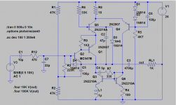
This buffer is a building block of a high resolution audio measurement system, and it will have to process a range of frequencies centered around ~100KHz with sub-ppm linearity, ideally sub-ppb, hence the "complexity" (which is quite relative and moderate considering the performances)
An opamp, driving a class A buffer in the loop will get you to 100 ppb - so about 15x better than an AP272 . . .
It is worth triying, I'll make a test tomorrowIf it helps, just by playing around with your circuit trying to make it oscillate in LTspice using possible stray capacitance and wiring inductance values, a 20pF or higher capacitance between Q5 collector and the output combined with 100nH between the top of R8 and D1 in the +ve supply line induces VHF oscillation.
Playing around again but this time to try and stop the oscillation with as low a value cap as possible, the most effective place was 15pF between Q2 base and Q5 emitter.
I'll try it too, but I think it will stop oscillations: the final effect is comparable to the feedforward cap I tried earlierPerhaps simplifying the circuit to get some data would be helpful.
SWAG-the bias loop Q4-Q3 thru the main amp xistors (Q2-Q1) up through Q5 could be unstable.
What if, just as an experiment to test that theory, you broke that loop? Simplest way that preserves the most parasitics, might be to
1. temporarily short out D1 and D2
2. place a 500 Ohm resistor from the out node to ground to get pull down current.
If it stabilizes things, it might give you a hint as to where to go next.
I don't know of any opamp capable of <10e-7 at over 100KHzAn opamp, driving a class A buffer in the loop will get you to 100 ppb - so about 15x better than an AP272 . . .
All the capacitors are solid tantalum, they combine very low ESL with moderate ESR, the best mix for damping.Elcos tend to be inductive on high freq. , how about C2?
I assembled an opa1611 driving a lme49600 on Friday and did some testing yesterday.An opamp, driving a class A buffer in the loop will get you to 100 ppb - so about 15x better than an AP272 . . .
Squarewaves good from 1kHz to 100kHz.
But at 10Hz there is some slope (~20% of signal) on the "flat" sections. I think this indicates roll off of ~-2.4dB @ 10Hz.
Yet there is no input filtering. It is DC coupled through out !
There is a sort of in-built mechanism for checking, through intermodulation (which is basically the same as THD, just generalized to any frequency).A sub-ppm buffer at 100kHz.... how do you plan to verify this once it's debugged? Just curious....
If I detect IM products downstream, it will mean the buffer is not up to the task.
It seems to work, as I have already had to rule out all current high perf opamps I could get hold of.
Think of PIM measurements: the test instruments need to be OK for sure, but then the measurement floor can be much lower.
I habitually use AC coupled input.^
Looks like o'scope prob (AC-coupled, mabye AC/GND/DC switch is broken). Does the generator signal look OK?
-----:-----
A sub-ppm buffer at 100kHz.... how do you plan to verify this once it's debugged? Just curious....
I'll check again on DC input.
I'll just accept the lme49600 datasheet info: 0.00003% (300ppb)
It's only a headphone driver/buffer.
All the capacitors are solid tantalum, they combine very low ESL with moderate ESR, the best mix for damping.
And power supply, how it looks like?
OK, I have found the time to make some tests
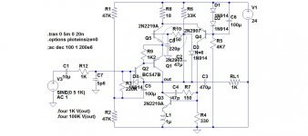
But this negative opened up new possibilities; in fact only one is left: the cascode stage. I disabled Q5, and bingo, oscillations were gone!
Since this type of cascoding has nothing unusual and works properly most of the time, it is probably the combination cascode + CFP which has such a weird effect, so weird that the sim didn't catch it.
With this knowledge, I concentrated my efforts on Q5, but the problem seems exceptionally persistent: I tried base and emitter stoppers, and even with a combination resistor + ferrite bead, it wouldn't go away. If anything, the remedies seem to make things worst.
I'll have to think about it overnight, try to figure out what's going on. Very strange.
This one had no effect, nothing positive anyway.Playing around again but this time to try and stop the oscillation with as low a value cap as possible, the most effective place was 15pF between Q2 base and Q5 emitter.
Quite surprisingly, this one had no effect either. This was completely unexpected, as I imagined the current stasis loop played a big role in the instabilities.What if, just as an experiment to test that theory, you broke that loop? Simplest way that preserves the most parasitics, might be to
1. temporarily short out D1 and D2
2. place a 500 Ohm resistor from the out node to ground to get pull down current.
If it stabilizes things, it might give you a hint as to where to go next.
But this negative opened up new possibilities; in fact only one is left: the cascode stage. I disabled Q5, and bingo, oscillations were gone!
Since this type of cascoding has nothing unusual and works properly most of the time, it is probably the combination cascode + CFP which has such a weird effect, so weird that the sim didn't catch it.
With this knowledge, I concentrated my efforts on Q5, but the problem seems exceptionally persistent: I tried base and emitter stoppers, and even with a combination resistor + ferrite bead, it wouldn't go away. If anything, the remedies seem to make things worst.
I'll have to think about it overnight, try to figure out what's going on. Very strange.
Here's another experiment that might further the divide and conquer strategy.
With the stasis loop disabled as described in my earlier email, you report that the oscillation remains. You also report that eliminating the cascode transistor
Q5 stops the oscillation.
Perhaps you've done essentially this already with the base and emitter stoppers...but, what happens if you remove C2 while the cascode transistor is still in place?
Member
Joined 2009
Paid Member
Perhaps, but the original circuit looked stable too. Meddling with the current loop without modifying the cascode will only have minor effects, if anyThis one "looks" stable in simulation..
This will essentially leave the 6 diode's dynamic resistance as base stopper.Perhaps you've done essentially this already with the base and emitter stoppers...but, what happens if you remove C2 while the cascode transistor is still in place?
I suppose that at some level, it will manage to kill the oscillations, but at the cost of the HF performance, which is important in my case
6.8Ω + 270nH ferrite beadHow much emitter degeneration did you add to Q5 ?
This will essentially leave the 6 diode's dynamic resistance as base stopper.
I suppose that at some level, it will manage to kill the oscillations, but at the cost of the HF performance, which is important in my case
That's true...it will affect the high freqs, but if it succeeds (or fails) in stopping the oscillation, it may give insight into a better way to find an answer that you can live with.
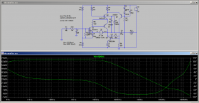
Voltwide had a good observation. I repeated his test and found:
1. disabling the cascode helped phase margin a little, but it was still kind of iffy.
2. Adding 100 pF from collector to base of Q1 gets pretty good phase margin.
Of course, if the sim and reality agree...that remains to be seen!
1. disabling the cascode helped phase margin a little, but it was still kind of iffy.
2. Adding 100 pF from collector to base of Q1 gets pretty good phase margin.
Of course, if the sim and reality agree...that remains to be seen!
The input transistor Q2 acts as voltage amplifier with collector-base capacitance producing miller effect:
-Input impedance is more of a capacitor, i.e. drops linearly with signal frequency
-loop bandwith is limited by base series resistance R12 and varies with actual source impedance Rg.
For maximum Bandwith R12+Rgen < 10Ohm!
But this is not what I expect from a voltage buffer amp
-Input impedance is more of a capacitor, i.e. drops linearly with signal frequency
-loop bandwith is limited by base series resistance R12 and varies with actual source impedance Rg.
For maximum Bandwith R12+Rgen < 10Ohm!
But this is not what I expect from a voltage buffer amp
- Status
- This old topic is closed. If you want to reopen this topic, contact a moderator using the "Report Post" button.
- Home
- Amplifiers
- Solid State
- Unstable buffer