I've been setting the input transistor bias current to around 2 mA with the J112, so I assume we need at least that. I've been looking at the datasheet, and also wondering if the on resistance, Rds(on) is an issue.Maybe some other type of LND, this one has just too low Id (1,6 mA) at Vgs= 0 V, altough its NTC character is welcome here.
Maybe some other type of LND, this one has just too low Id (1,6 mA) at Vgs= 0 V, altough its NTC character is welcome here.
I've been setting the input transistor bias current to around 2 mA with the J112, so I assume we need at least that. I've been looking at the datasheet, and also wondering if the on resistance, Rds(on) is an issue.
Yes, as I look into it a little deeper this one has too low an Id for our purposes. It just initially looked like a potential option for places where JFET like behaviour, as it applies to the CCS, at higher voltages appeared to be useful. The others in the product line seemed to have way too high an Id; the next product jumped to 120mA for Id and went up from there. I don't know if that is really an issue since we set the current using a resistor anyway.
Yes, thanks for asking.
I will be sending out payment requests by PM tomorrow, and the first boards from this order will ship on Monday.
To everyone who will be making payments by Paypal:
1) You correct shipping address must be either in Paypal, or in the comment field of your payment. Orders without addresses take more emails, and therefore more time.
2) Please include your diyaudio name, and number of boards you are ordering, so the payments can be matched easily to the list.
Thanks!
How much is it in total with shipping to Belgium?
Yes, and there will probably be another smaller order in 1~2 weeks.Are any boards in this batch still for sale?
Geo
Yes, just keep an eye on that thread.Hi PMI, my payment is sent, thanks.
On another matter are you thinking of doing another group buy for the capacitor multiplier supply boards.
Regards
Unfortunately the US Post Office is tightening the rules for what can be sent as regular mail, even if it fits into a large envelope. That makes combining shipping less desirable, because the postage goes from around $4~5 to $12 in one step. Equally annoying, anything sent as a package requires a Customs form, so that makes it extra work.
CCS and the J112 jfets.
I've had a couple questions about using the CCS and the J112 jfets.
It has been discussed before, but here is a summary:
First - The Jfets are included with all boards at no extra charge. There are 2 per board, so 4 J112's with each set of two boards. They only cost about 10 cents in quantity 100 at Mouser, compared to 50 cents or up to a dollar each in small quantity. The J112 is an N-channel Jfet.
The PCB is laid out so those who want to avoid an extra transistor, or just experiment with a current injection resistor can do so. In that case, a small jumper (short) has to be installed across the Jfet pads.
There is plenty of discussion about the CCS in Lazy Cat's main VSSA thread, and more discussion about how to calibrate the circuit without a CCS with just a resistor in the PeeCeeBee thread by Shaan.
Once calibrated using the trim pots, the CCS current will be about 2 mA, and it will stay constant over the normal line and load variations of the power supply voltages.
When using a resistor, the resistor value should be chosen such that it produces about the same current at the intended supply voltage. For example, +/-35V supply -> ~18K, and then adjusted using a trim pot or another resistor during calibration.
I found something interesting in the TI LM-4702 AN concerning gate resistor values for good square waves for different output devices. I'm not sure how applicable it is to this situation but the more knowledgeable of you can decipher it for the rest of us. In chapter 9 it specifies values for different output devices which could effect the HF qualities of the amp.
http://www.ti.com/lit/an/snaa045a/snaa045a.pdf
http://www.ti.com/lit/an/snaa045a/snaa045a.pdf
Boards arrived today, they look nice.
I will run the curves either later tonight or over the weekend on the KSA / KSC devices and see how closely they match up. I am waiting for some components to arrive for these but will post results as I'm able.
Mine have not arrived yet...

I guess the time at customs is not always the same...
Fab
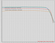
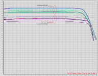
The Hfe is clearly lower when measured cold than when measured after the temperature has stabilized. I also did not have much trouble finding closer matches when measured warm, so perhaps that requires a bit of exploration.The curves for the unsorted devices.
I am really happy to see that the curve is flat over such a wide range of Ic, btw. I have no way of showing that with manual measurement.
This curve tracer seems like an excellent find!
edit:
This also clearly shows we should not be setting the bias above 20 mA. I had pretty much figured that out by experimenting, but did not want to say it because I had no measurements to prove it... now we do!
Last edited:
- Home
- Amplifiers
- Solid State
- VSSA Through-Hole-PCB build thread