Hi Terri can't bear more VSSA bad luck for you, so little comment on new VSSA i see one input terminal not sitting well, take care if screwing to hard that soldered legs not gets cold connection. And maybe return ground and speaker wire would be better more away from sensitive input stage......I have both yours and Jason's playing side by side and hooked up to an A/B switch. They are very close in sound but not exactly. There is just a slightly different voicing between the two. You have to listen closely to hear it. I will assume it is mostly the caps breaking in. Jason's boards have a couple days play time and of course yours are spanking new. Still fun comparing.
.....
Congratulation with two times VSSA running, it's like a book/film with happy ending thanks to Terri, Jason and Pete.
Thanks Pete and members here, very interesting thread i follow with pleasure.
Hi Still4given
By curiosity can you provide your feedback caps info (brand, type).
I can see that it is not the Nichicon FG that Lazycat recommends. For mine I use so far Nichicon Bipolar EP series. Once I get my boards from PMI I intend to use the FG for comparison purpose. From what I remember Lazycat found interesting differences in sound using different feedback caps... So you may try this as well...
Fab
I 'm not sure which are the feedback caps but I used these for C17,18. I't been playing all day and it sounds better the longer it plays. The differance between the two is getting slighter. I will wait to install this in a case until more is discovered.
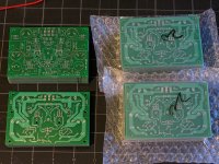
The terminal block is sitting crooked because Pete set the board for a very small terminal block so I had to drill new holes to fit mine. On the first board I tried to use one of the existing holes and just drill a second which ended up having the block sitting in a skewed manner. On the second one I just drilled two new holes so It sits in line. They are hardwired on the back. I can't speak to the layout. That is Pete's baby but I can tell you that it is dead quiet, no hum at all.
Blessings, Terry
Hi Terri can't bear more VSSA bad luck for you, so little comment on new VSSA i see one input terminal not sitting well, take care if screwing to hard that soldered legs not gets cold connection. And maybe return ground and speaker wire would be better more away from sensitive input stage.
The terminal block is sitting crooked because Pete set the board for a very small terminal block so I had to drill new holes to fit mine. On the first board I tried to use one of the existing holes and just drill a second which ended up having the block sitting in a skewed manner. On the second one I just drilled two new holes so It sits in line. They are hardwired on the back. I can't speak to the layout. That is Pete's baby but I can tell you that it is dead quiet, no hum at all.
Blessings, Terry
I am referring to the electrolytic caps C7/C8.
ThankS
Fab
.....The terminal block is sitting crooked because Pete set the board for a very small terminal block so I had to drill new holes to fit mine. On the first board I tried to use one of the existing holes and just drill a second which ended up having the block sitting in a skewed manner. On the second one I just drilled two new holes so It sits in line. They are hardwired on the back. I can't speak to the layout. That is Pete's baby but I can tell you that it is dead quiet, no hum at all.....
 explanation for terminal block. It was not layout i meant, in pictures you have two loose wires with up to high current resting/passing thruu area with input pair, maybe doesn't matter but i would route them in other direction. Thanks for nice pictures/reports.
Oh I see. That is only because I have it all hooked up on the table and the speaker wires are hanging off the side of the table. I will route them away. I am always careful to keep them seperate when in a case.
I am referring to the electrolytic caps C7/C8.
I used these. I suppose I could have used something more expensive.

Blessings, Terry
The Panasonic FR-series is actually quite good. I used them on the previous revision of the board, and I am still using it as the main decoupling cap on this version.
Good point about the terminal block.
It is a 0.1", or 2.54-mm (2.50 will also work) lead spacing 90-degree entry terminal block.
Examples, with Mouser Prices.
Phoenix Contact p/n 1725656 ($1.20)
TE Connectivity/Buchanan p/n 282834-2 ($0.35)
The Phoenix version is better quality, but I wish it did not cost over $1.
I experimented with the wiring quite a bit, since I have three different versions....in pictures you have two loose wires with up to high current resting/passing thruu area with input pair...
The output and speaker return are a potential issue, I agree, but so far only that, potential.
The wires from the transformer to the power supply rectifier input are the main risk. The rectifier diode switching noise is the greatest source of radiated noise so far. If the input leads come close to those wires, or to the side of the transformer where the secondary winding leads exit the transformer, noise appears on the output, in synch with the peaks of the ripple before the filter.
If an oscilloscope is line-triggered (on the Mains Frequency), one can clearly see those small peaks (spikes) appearing above the general background noise on the output, and perfectly aligned with the switch-off time of the rectifier diode.
Using shielded input leads helps to reduce that source of noise to almost nothing, but nevertheless, those are the wires I would keep away from everything else, and short as possible. I believe Lazy Cat may have also mentioned shielded input wires somewhere.
As you can see in my pic in post 179 with the two VSSA side by side that I just hooked them up quick and dirty, No twisted power leads and yet they sound lovely. Can't wait until they are in a case with all the leads dressed. I haven't shortened any of the transformer wires yet because I haven't settled on them yet. I will probably get a bigger transformer for this new VSSA because I want to try it on a higher rail. Having fun. Thanks Pete!
You are very welcome...As you can see in my pic in post 179 with the two VSSA side by side that I just hooked them up quick and dirty, No twisted power leads and yet they sound lovely. Can't wait until they are in a case with all the leads dressed. I haven't shortened any of the transformer wires yet because I haven't settled on them yet. I will probably get a bigger transformer for this new VSSA because I want to try it on a higher rail. Having fun. Thanks Pete!
I saw several pics of your bench, so I understand the wiring. I made the post above, b/c BYRTT jogged my memory about which wires seemed to cause the most potential trouble when I was running tests. His posts often make me think... although at 12 am, a bit slowly...
It makes sense, when you think about it: During normal play, the signal amplitude on the output leads is not that big. The voltage on the transformer secondary leads stays close to 70V pk-to-pk When the rectifier diodes start conducting, there is a current spike. When they stop conducting, there is a voltage spike.

Thanks! Your boards and parts were shipped. Those came from the first batch, same as Terry's.Hope so. Got some outputs on the way, so we should have some action in a while.
@PMI - those alternative VAS devices are on the way via regular air mail.
Good News.!
i have just busted my drill bit, so awaiting another one.
Ref: My DIY Board based on yours, It makes a nice 'Looking' board, but Man are those holes Small & hard to solder without the thru hole plating. ( or more likely, it's just Me ) or possibly the Cheap Boards. This problem was on the.032" 1/2oz board. Was drilling out the .064" board when i broke the bit.
i have just busted my drill bit, so awaiting another one.
Ref: My DIY Board based on yours, It makes a nice 'Looking' board, but Man are those holes Small & hard to solder without the thru hole plating. ( or more likely, it's just Me )
or possibly the Cheap Boards. This problem was on the.032" 1/2oz board. Was drilling out the .064" board when i broke the bit.Here is a device data sheet I found. Looks like a possible higher voltage option to the typical jfet.
http://www.supertex.com/pdf/datasheets/LND150.pdf
Might be useful, here or elsewhere.
http://www.supertex.com/pdf/datasheets/LND150.pdf
Might be useful, here or elsewhere.
Yes, thanks for asking.PMI , in post 29 I ordered 2 boards to I've to pay now?
I will be sending out payment requests by PM tomorrow, and the first boards from this order will ship on Monday.
To everyone who will be making payments by Paypal:
1) You correct shipping address must be either in Paypal, or in the comment field of your payment. Orders without addresses take more emails, and therefore more time.
2) Please include your diyaudio name, and number of boards you are ordering, so the payments can be matched easily to the list.
Thanks!
Here is a device data sheet I found. Looks like a possible higher voltage option to the typical jfet.
http://www.supertex.com/pdf/datasheets/LND150.pdf
Might be useful, here or elsewhere.
Maybe some other type of LND, this one has just too low Id (1,6 mA) at Vgs= 0 V, altough its NTC character is welcome here.
- Home
- Amplifiers
- Solid State
- VSSA Through-Hole-PCB build thread