- Toroidal Transformer, 34mm x 81mm, 50 VA, 230V, 2 x 15V, Single Primary, Dual Secondary, Open
- 2 AIYIMA LM317 rectifiers
- 10 k potmeter logaritmic
- Yellow brown is power, brown is + yellow -
- Audio red is right + and left is black + and white is ground
Well, the power has only 2 wires, and the audio input also where 3 are needed?? At Q9 I had to take it out and turn it around, it didnt work out esthetically but it is connected now, however the tripod got quite hot...
Right now I doubt if I can fix this, there was this Dutch man here on the forum, I want to ask him for help.


Bert,
For sure your DC power to the preamp board is wired wrong.
The power transformer may be wired correctly but since the colours for the transformer windings are not known to me, I cannot verify. Please post information on power transformer wire colours.
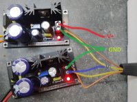
As for the DC power supplies, the output from the two boards need to be wired to output V+, Gnd, V-. See attached picture. Both PS boards need to be connected to provide the V+, Gnd, V-, and this power is to be supplied to both channels of the preamp.
Use a meter to confirm the voltages before connecting the PS to the preamp boards. With a meter set to VDC, place the black probe on the PS Ground, and the red probe on V+. The meter should display a positive voltage. Change the red probe to V-. The meter should display an equal but negative voltage.
For sure your DC power to the preamp board is wired wrong.
The power transformer may be wired correctly but since the colours for the transformer windings are not known to me, I cannot verify. Please post information on power transformer wire colours.
As for the DC power supplies, the output from the two boards need to be wired to output V+, Gnd, V-. See attached picture. Both PS boards need to be connected to provide the V+, Gnd, V-, and this power is to be supplied to both channels of the preamp.
Use a meter to confirm the voltages before connecting the PS to the preamp boards. With a meter set to VDC, place the black probe on the PS Ground, and the red probe on V+. The meter should display a positive voltage. Change the red probe to V-. The meter should display an equal but negative voltage.
Attachments
At Q9 I had to take it out and turn it around, it didnt work out esthetically but it is connected now, however the tripod got quite hot...
Use an alligator clip, clip it on the lead of the transistor your soldering or desoldering as a heat sink.
Right now I doubt if I can fix this, there was this Dutch man here on the forum, I want to ask him for help.
Listen to Ben Mah and follow his step by step instructions and you WILL fix it. If you look back at this thread you will see how many members Ben Mah has helped fix their BA2018 Line Stage.
As there were no labels on the resistors (a bit of a bummer) so I measured all of them
Always measure first, the label on the resistors are in code, here is a link to the DigiKey website to decipher.
https://www.digikey.com/en/resource...ors/conversion-calculator-resistor-color-code
elwood, you are giving me more credit than I deserve. I have helped many people with their B1 Korg preamp but as for the BA2018 linestage, it is not one that I have much experience and understanding. So others with more knowledge and experience will need to help if the preamp does not working properly once the power supply is sorted out.
Yeah, the store's description page ( https://diyaudiostore.com/pages/project-ba2018-linestage ) does indicate "Advanced Difficulty". I would recommend adding something like "SMD soldering required" as well.
With my limited experience I need the use of flux and quite fine solder wire for even large-ish SMD parts like the 2sk209. A DIYer who has only done through-hole soldering might not have these, which may make it more difficult.
And don't forget to carefully clean the flux residue. Don't ask how I know.")
With my limited experience I need the use of flux and quite fine solder wire for even large-ish SMD parts like the 2sk209. A DIYer who has only done through-hole soldering might not have these, which may make it more difficult.
And don't forget to carefully clean the flux residue. Don't ask how I know.
So I need something like this, with plus > min > groundBert,
For sure your DC power to the preamp board is wired wrong.

Bert - Once you have a proper power supply ready (+V,GND,-V), I would just focus on one channel at a time. For setup on a pre or power amp, I short all inputs to ground (+IN and -IN to GND). You will connect a voltmeter between OUT and GND to watch the DC voltage there. The trimmers P1 (and P2 on other channel) should be adjusted for the lowest output DC voltage (a few mV wiggling around is ok).
If this DC offset voltage is way out (lots of volts, or can't adjust, etc), troubleshooting will be needed obviously.
In normal operation, you need to short -IN to GND at CN2,CN4 if you will be using just a single ended input. Refer to post #4,213 again if needed. Your signal input will go to +IN and GND.
Last edited:
Well, if I could do it, others can, too.I do not consider this preamp a sensible first build.
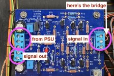
@_Bert_ me not wanting to be not only joky, here's a bit an explainer how to wire up the pre-amp (once you got the rectifier situation set)
Attachments
Last edited:
Excellent suggestion.I would recommend adding something like "SMD soldering required" as well.
You do not need a new board. Simply wire the ones you have just like Ben Mah showed in the picture on post#4222.So I need something like this, with plus > min > ground
Bert, As RickRay said, just wire the two supplies as shown in post #4222. That will give V+, Gnd, V- which will go to each preamp board. Test the wired up power supply before connecting to preamp boards. Then connect to only one preamp board at a time to check.
Okay, I wired like you showed on the picture, first I put the output at 15 volts exactly on both regulators. I tested both channels separately and they work!Bert,
As for the DC power supplies, the output from the two boards need to be wired to output V+, Gnd, V-. See attached picture. Both PS boards need to be connected to provide the V+, Gnd, V-, and this power is to be supplied to both channels of the preamp.
Use a meter to confirm the voltages before connecting the PS to the preamp boards. With a meter set to VDC, place the black probe on the PS Ground, and the red probe on V+. The meter should display a positive voltage. Change the red probe to V-. The meter should display an equal but negative voltage.
But the volume potentiometer did not work, and distorted one channel, but without both channels were clear and loud. Do I need a 10k logarithmic or linear potmeter?
I used 1 short wire to bridge with the other output and 1 wire to the preamp but that didnt work, both needed seperately and similar. All my assumptions are wrong. I got it working now! ↓ Meanwhile, thankyou all!Post a picture of the power supplies. Did you test it without the preamp boards attached?
Long distance trouble shooting is difficult. Please be specific and detailed when describing what you did and the results.
- Home
- Amplifiers
- Pass Labs
- Wayne's BA 2018 linestage