I don't want to get embroiled in another debate on semantics, but it seems to me that in our context "modes" generally refers to phenomona of standing waves from a multiple reflection wave path. It could be the air path between a pair of boundaries or the vibration pattern of a woofer diaphragm, a mode would be a frequency and its unique vibration pattern, complete with nodes and maxima.
The modes are the frequencies where an integral or even fractional number of wavelengths fit into the physical or electrical object, setting up a repeating pattern. I wouldn't apply the term to reflections from a single boundary.
Anyhow, the discussion was about the power response impact of a driver near a boundary.
David
I use the term "mode" in a very broader context. For example sound radiation can be done "modally" (Monopole, dipole, quadrapole, ...), but there are no standing waves or nodes (well there are sort of nodal surfaces to a radiation mode). A "modal" solution to any physical problem comes about when the answer can be shown to be the sum of a number (usually infinite) of more fundamental functions, which are usually called "modes". In a closed room the modes are standing waves - well standing if there is no absorption, otherwise they are a combination of a standing wave and a propagating wave.
An electron which has been captured by a nucleus becomes modal, but if it is in free space then it is not modal. Modes virtually always come about as the result of applying some form of boundary condition to an equation. Modes only occur for certain types of boundary conditions.
An electron which has been captured by a nucleus becomes modal, but if it is in free space then it is not modal. Modes virtually always come about as the result of applying some form of boundary condition to an equation. Modes only occur for certain types of boundary conditions.
I've been giving this some thought and there is something that's bothering me.This kind of gets us back to the radiation resistance subject that we debated some time back. Put a pair of sources in space and measure them from a position equidistant from both. Pressure doubles, or the response curve goes up 6dB.
6dB would be 4 times the power, so where did the power increase come from (an efficiency doubling if we doubled the input by having 2 speakers)? Answer: mutual coupling or an increase in radiation resistance. Is it doubled? Depends on whether the sources are near to each other or not. Consider them as two independent sources and find the spherical power average around them. If it is less than 6dB greater than one source (or perhaps it is 6dB at low frequencies and less at higher frequencies) then the difference is a directivity gain.
In all cases the axial gain from two sources is 6dB. The 6dB must be the sum of the radiation impedance rise and the directivity rise (usually primarily radiation impedance at low frequencies and directivity at high).
So we talk about this mystical factor of radiation impedance gain or mutual coupling, but we calculate it simply by an integration of 2 independent sources.
If you have two woofers in free space that are near each other there will be a 6dB increase over one. As you say, is that coming from mutual coupling or directivity increase ?
For everything to add up it has to be directivity increase at large spacings (1/2 wavelength and greater?) progressively changing to mutual coupling as spacing is reduced. (Change in effective radiation resistance)
Somewhat conveniently this calculates to 6dB measured equi-distant regardless of woofer spacing, something I'm willing to accept.
However as you also point out, in the two woofer case 3dB of that is coming from the fact that you're doubling input power - if you go from one 8 ohm woofer driven with 1 watt to two 8 ohm woofers in parallel the total system is now being driven with 2 watts, so only 3dB of the 6dB increase is an actual gain from having two speakers. Actual efficiency has only increased 3dB.
However if you place a woofer close to a floor boundary that is nearly 100% reflective you'll also get a 6dB increase, and at first glance its easy to say that the "image" woofer below the floor does exactly the same thing as a real second woofer would if there was no floor there. (Image models more or less take that for granted)
But does it really ? I don't see how, because you still only have one actual woofer driven by the same amount of total power, so the gain actually IS 6dB, you still only have 1 watt input for a 6dB increase in SPL instead of 2 watts input for a 6dB increase in the 2 speaker free field case.
So the question is, where is the 6dB coming from ? Obviously if its large enough the floor causes the speaker to be radiating into half space instead of full space, and just like a baffle above the baffle step frequency this will give a 3dB gain in directivity. (The difference with an infinite floor boundary being that everywhere in the room you could measure is within the directivity beam-width because only "under" the floor is excluded)
What about the other 3dB ? Again, if its the same as a baffle, the other 3dB must come from the change in radiation resistance a woofer sees between full space and being mounted at a half space boundary - the fact that its at 90 degrees to the floor doesn't matter at low frequencies if its very close.
Where I'm leading with all of this is that the floor itself if in close enough proximity must indeed be altering the radiation resistance seen by the woofer, to the tune of 3dB worth of output increase. (With the remaining 3dB being a result of sectioning full space into half space)
If close proximity to the floor which is close enough for the driver to be close to in phase with the reflection over the frequencies of interest means that radiation resistance alters, then surely being at 1/4 of a wavelength from the floor will indeed result in a change in the radiation resistance seen by the woofer and therefore potentially up to a 3dB reduction in power response relative to an "at boundary" mounting of the woofer ?
Could Roy Allison actually have a point after all about the radiation resistance and therefore power response changing as the woofer to floor spacing is increased to 1/4 wavelength ?
I still don't believe that the cone movement will be changed in any significant way, but that is not required for the radiation resistance to change and the efficiency to be altered - as happens with stacked woofers. (They move the same amount in each others presence but there is a net efficiency increase per watt)
Last edited:
For everything to add up it has to be directivity increase at large spacings (1/2 wavelength and greater?) progressively changing to mutual coupling as spacing is reduced. (Change in effective radiation resistance)
This is basically correct.
I still don't believe that the cone movement will be changed in any significant way, but that is not required for the radiation resistance to change and the efficiency to be altered - as happens with stacked woofers. (They move the same amount in each others presence but there is a net efficiency increase per watt)
In air this is basically true as well, but that's because air is so soft and the radiation load is so insignificant. In underwater acoustics the story is quite different. Mutual coupling can actually cause a negative load on some units of a large array of transducers and they have been know to blow up as a result. This has to be taken into consideration in the design.
Yes, I'm making the assumption of air and the fact the radiation load is so insignificant.In air this is basically true as well, but that's because air is so soft and the radiation load is so insignificant.
It's also different with gain in antennas through stacking since radiation resistance of space is the primary source of energy loss in an antenna and coupling to free space is very good.In underwater acoustics the story is quite different.
(Unlike speakers hovering around ~1% most resonant antennas are very efficient at 80-90% or so, so gain can only be achieved through directivity)
Interestingly with most antennas maximum stacking gain occurs around 1/2 wavelength (actually slightly more) spacing due to directivity, as spacing is reduced so is stacking gain as there is no corresponding increase in efficiency through radiation resistance change to keep the on axis output the same. (In fact it goes down a bit because of detuning from both antennas coupling too closely)
The fact that two speakers continue to show a 3dB increase in output as spacing is reduced below 1/2 wavelength but antennas don't I think is also proof that the increase seen with two speakers less than 1/2 wavelength apart is an actual efficiency increase that must be coming from mutual coupling altering the radiation resistance.
In an antenna there is almost no more efficiency to be had, while a speaker is extremely inefficient to begin with due to the poor coupling to the medium.
Last edited:
I think we covered this way back in the thread, but it is always a bit shakey in my mind and worth thinking through again.
I fully agree that a two woofer case and awoofer near boundary case are one and the same. We can't cross from our side of thboundary to the other but otherwise we can't detect any difference.
As to the 3 vs. 6 dB case, I was thrown when I first saw Allison's curves with 3, 6 and 9 dB gain from 1 , 2 and 3 boundaries. Of course we see a 6 dB gain with a woofer near a boundary, but can only see it in half space, so the 6 dB from a boundary is ony a doubling, or 3 dB gain in real power. Allison was correctly showing the power gain.
I think I referenced a few papers on the subject of multiple woofers. One was by Keele where he was comparing multiple woofers to short horns and finding that multiple woofers weren't far of in efficiency and superior in bandwidth. He also looked, in another paper, at how far we could go with efficiency of a direct radiator if all the parameters were freely manipulated. There is an absolute maximum when our usually insignificant air load starts to get very significant. A later paper from JBL (Gander, I think) looked at much larger arrays of woofers to see how efficiency would gain as the qty. grew.
In reading those it became evident that adding woofers, at least initially, would double effective efficiency for every doubling of woofer number. Axial pressure always doubles for unit doubling, at least while the overall combined source size isn't huge. When the source grows too big the added sources have to be around the perimeter and have greater distance to you and start contributing less. That is, an infinite plane of drivers isn't any louder than a very large plane of drivers. Once the swarm is big enough you are in the near field of it and it's diminishing returns.
So if 6dB comes with every doubling of units, whether it is a power gain or not is found with the usual power summing integration. If the sources are less than a half wave seperated then they will sum in phase from any direction in a surrounding sphere. At higher frequencies this won't be the case and the power curve will deviate from the axial curve. By definition that must defined the d.i. curve (axial curve minus power curve).
So doubling the number of units doubles pressure on axis. If it is a full quadrupling of power then we say the radiation resistance has doubled (for each driver) if not then the directivity gain makes up the difference.
David
Ran across an interesting paper the other day worth discussion.
http://downloads.bbc.co.uk/rd/pubs/reports/1995-04.pdf
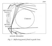
R. Walker of the BBC looked into the geometry of studio monitoring with the goal of creating surfaces around the monitors that made sure all early reflections bounced the sound rays well away from the listening position. He was aiming for no reflections within 20dB of the direct sound for the first 20 msecs. He later found that 15dB for the first 15 msecs was generally good enough.
Since specular reflection isn't a great assumption for lower frequencies he had the computer look for surfaces that kept the rays well away from the listener, outside a surrounding circle.
A big part of his motivation was that the studio users weren't happy working in overly dead studios. This approach let them cut back strongly on the amount of absorption they used.
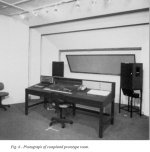
He verified the results with listening tests, energy time curves and 3D frequency response (FR vs. time).
David S.
http://downloads.bbc.co.uk/rd/pubs/reports/1995-04.pdf
R. Walker of the BBC looked into the geometry of studio monitoring with the goal of creating surfaces around the monitors that made sure all early reflections bounced the sound rays well away from the listening position. He was aiming for no reflections within 20dB of the direct sound for the first 20 msecs. He later found that 15dB for the first 15 msecs was generally good enough.
Since specular reflection isn't a great assumption for lower frequencies he had the computer look for surfaces that kept the rays well away from the listener, outside a surrounding circle.
A big part of his motivation was that the studio users weren't happy working in overly dead studios. This approach let them cut back strongly on the amount of absorption they used.
He verified the results with listening tests, energy time curves and 3D frequency response (FR vs. time).
David S.
Attachments
Wow, I was thinking about doing something like this, and this seems encouraging. But I think the dissatisfaction of overly dead rooms tend to reveal deficiencies in other parts of the audio chain.Ran across an interesting paper the other day worth discussion.
http://downloads.bbc.co.uk/rd/pubs/reports/1995-04.pdf
R. Walker of the BBC looked into the geometry of studio monitoring with the goal of creating surfaces around the monitors that made sure all early reflections bounced the sound rays well away from the listening position. He was aiming for no reflections within 20dB of the direct sound for the first 20 msecs. He later found that 15dB for the first 15 msecs was generally good enough.
Since specular reflection isn't a great assumption for lower frequencies he had the computer look for surfaces that kept the rays well away from the listener, outside a surrounding circle.
A big part of his motivation was that the studio users weren't happy working in overly dead studios. This approach let them cut back strongly on the amount of absorption they used.
He verified the results with listening tests, energy time curves and 3D frequency response (FR vs. time).
David S.
But I think the dissatisfaction of overly dead rooms tend to reveal deficiencies in other parts of the audio chain.
I think there's some degree of truth in that. There are certain types of speaker deficiencies that are somewhat masked by an overly reverberant live room, cutting down the reflections in the room will tend to reveal those a bit more. A good speaker shouldn't sound bad in a dead room.
Don't forget that he was actually achieving a more lively room. It was dead with regard to the early reflections from the speakers, but more lively than their usual over treated rooms. Still, the users later ranked .35 secs RT as better than .45 secs.
The idea is to specifically deal with the early reflections by sending them away from the listeners.
The idea is to specifically deal with the early reflections by sending them away from the listeners.
Dave and all
That is a fairly well know piece of work, and very reputable. I believe it is consistant with my point of view. In a lot of situations those design aspects are difficult to achieve. In a very small room like in a typical home such a design is not really feasible and as such one has to use directivity of the source to the maximum extent possible.
I also agree with the BBC, I don't like dead rooms, never did.

No takers on building to this concept, eh?
It answers what has been forward as an ideal in this thread: You can have a lively room and speakers of any directivity, including wide directivity, while still achieving a dead period in terms of early reflections.
The author gets lower early energy than you could achieve with diffusors. Probably lower than you could get with especially directional speakers. You could also use the concept with dipoles to good advantage. Since they send little energy to the sides where it would contribute to spaciousness, and much to the rear wall where it can cause problems, this approach would let you redirect the energy in a more beneficial direction.
You also don't need as complex a surface as this. If you have a well defined seating position you can simply put large reflectors at the wall bounce points of the reflections you want to "divert". Plus diffusors at points where you want reflections from (wide sidewall angles).
You could certainly experiment with free standing plywood reflectors, or even foam core.
David S.
No takers on building to this concept, eh?
It's certainly an interesting principle, however I suspect the WAF may not be sufficiently high for many
")
No takers on building to this concept, eh?
David S.
Dave
My ceiling diffusor is basically along these same lines and I can tell you that it works, although its not perfect, but its not very practical or easy to do. And WAF - forget about it!
I don't think that too many of us have "experimental listening rooms" that we can do this kind of thing in. I don't. My room is not big enough to accomodate anything like this along the side walls. And my room is way above average in size. As I said before, great idea, not very practical in a home situation.
- Status
- This old topic is closed. If you want to reopen this topic, contact a moderator using the "Report Post" button.
- Home
- Loudspeakers
- Multi-Way
- What is the ideal directivity pattern for stereo speakers?