As much as I like the concept and goal of constant directivity, the typical 2 way approach of constant directivity horn crossed over with a large mid-bass driver at the frequency where directivity is matched rather unfortunately puts the crossover in the middle of the midrange, lets say 1.5Khz.
You then have the same floor-bounce problems you have with a typical stand mounted 2 way design - put the speaker too close to the ground and imaging suffers, too high up and floor bounce is a problem.
To really solve the problem you need a crossover in the vicinity of 200-300Hz with the lower frequency driver at the floor and the higher frequency driver(s) a lot higher up.
Not really solvable with a 2 way CD design, and if you went to 3 way you then have the absurd problem of requiring two "woofers", one close to the floor which is actually producing the bass, and a second large one higher up which is only covering 300-1500Hz, but still has to be large to match the directivity of the horn...
Or perhaps a 2.5 way design ? Two identical woofers, floor height woofer covering 20-250Hz, upper woofer just below the horn covering 20-1500Hz, crossing over with the horn, that would eliminate floor bounce. If you matched it with the baffle step frequency there is your baffle step taken care of too.
Simon
I know what the design requires, I've laid out the requirements before (I even have an elliptical waveguide prototype), but I think that you have well stated my claim that it is "problematic". A thick rug on the floor is a lot easier and far far less costly.
I typically cross over much lower than 1500 Hz. Thats the point in my 8" speakers, but in the larger ones it is far lower. Not down to 300 Hz of course, that is "impractical".
And floor and ceiling bounces are not just LF problems. In fact I suspect that the LF aspects of these problems is far less than the HF aspects. So using a floor mounted woofer isn't really a solution IMO. In fact, IMO it doesn't really do much of anything.
Last edited:
Or perhaps a 2.5 way design ? Two identical woofers, floor height woofer covering 20-250Hz, upper woofer just below the horn covering 20-1500Hz, crossing over with the horn, that would eliminate floor bounce. If you matched it with the baffle step frequency there is your baffle step taken care of too.
OK, let's build one!

My point is its only "problematic" if you stick to a 2 way constant directivity design. If that's what you like to design that's a trade off you might have to accept, but that doesn't mean there aren't other approaches where it's a non-issue, and rather easy to solve.I know what the design requires, I've laid out the requirements before (I even have an elliptical waveguide prototype), but I think that you have well stated my claim that it is "problematic". A thick rug on the floor is a lot easier and far far less costly.
A more conventional 3 way design done properly can solve the problem for "free" just through appropriate choice of driver heights, crossover frequency, and network equalization. (The extra gain from the floor has to be taken into account for the low mounted woofer, eg less mid/tweeter attenuation than otherwise required...) A line array is another possibility.
A thick rug might help for the floor bounce caused by the incident reflection off the floor, (I actually had a large stuffed pillow on the floor in front of mine at one point doing a similar thing) but it does nothing for the floor/ceiling modal cancellation in the 100-200Hz range, which is usually far more severe and is taken care of by the floor mounted woofer.
If only I had the money to actually build any speakers at the moment...OK, let's build one!

I think your view of the floor bounce problem being unsolvable in the speaker design is tainted by looking through the glasses of constant directivity designs.
As much as I like the concept and goal of constant directivity, the typical 2 way approach of constant directivity horn crossed over with a large mid-bass driver at the frequency where directivity is matched rather unfortunately puts the crossover in the middle of the midrange, lets say 1.5Khz.
You then have the same floor-bounce problems you have with a typical stand mounted 2 way design - put the speaker too close to the ground and imaging suffers, too high up and floor bounce is a problem.
To really solve the problem you need a crossover in the vicinity of 200-300Hz with the lower frequency driver at the floor and the higher frequency driver(s) a lot higher up.
Not really solvable with a 2 way CD design, and if you went to 3 way you then have the absurd problem of requiring two "woofers", one close to the floor which is actually producing the bass, and a second large one higher up which is only covering 300-1500Hz, but still has to be large to match the directivity of the horn...
Or perhaps a 2.5 way design ? Two identical woofers, floor height woofer covering 20-250Hz, upper woofer just below the horn covering 20-1500Hz, crossing over with the horn, that would eliminate floor bounce. If you matched it with the baffle step frequency there is your baffle step taken care of too.
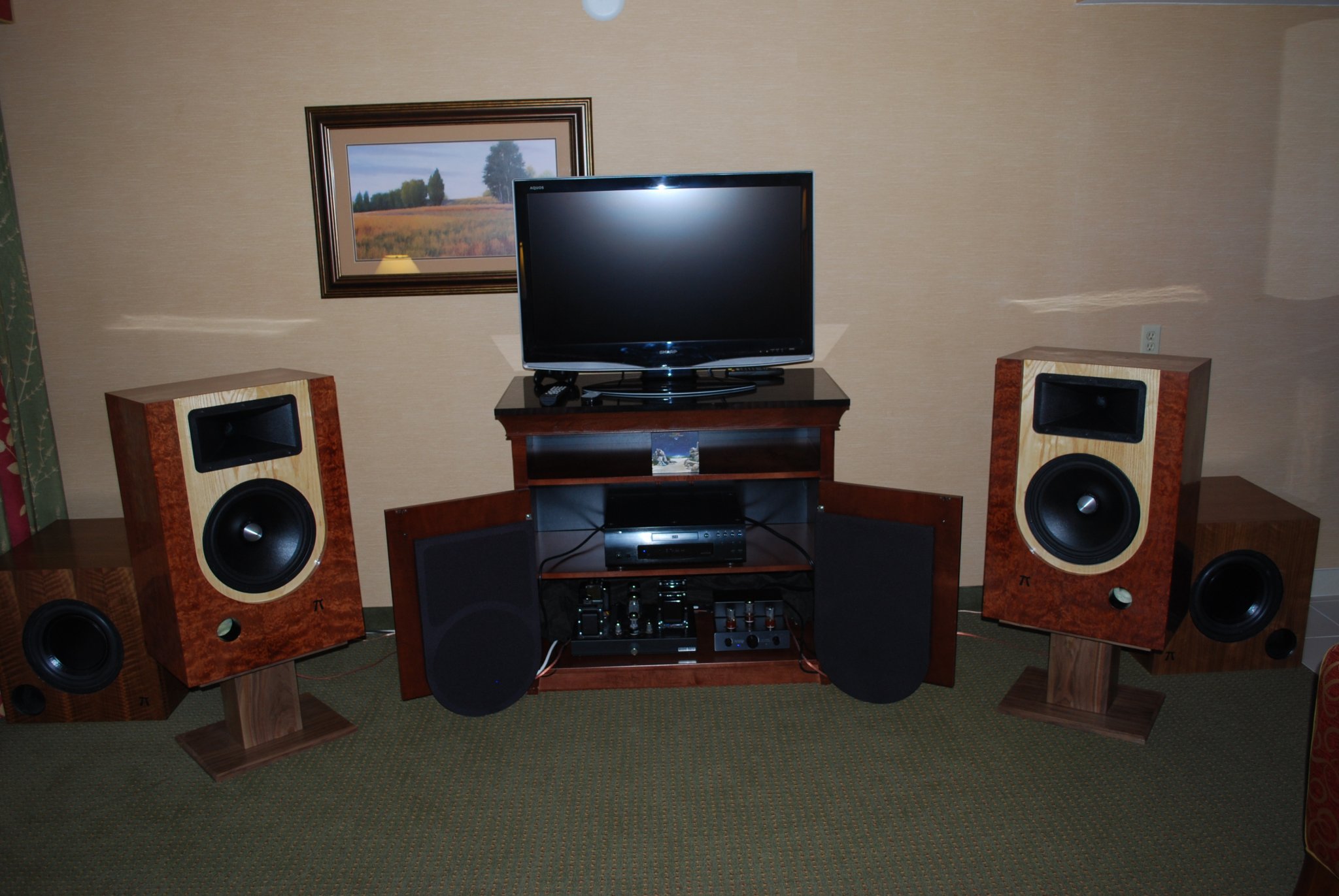
Agreed. The whole multisub concept is a speaker system design that seeks to solve a problem caused by room reflections. The flanking sub approach is pretty much the same thing, just at a slightly different scale because of the shorter wavelengths involved. I've implemented this approach with overlapping mids and woofers and with external "helper" woofers, placed near the mains they're flanking and blended with them through lower midrange, like this:
Then this is not a "small room". It takes a lot of open space for this to occur. That not the "assumption" that we are dealing with here.
What area would a small room have?
Wayne, that looks like your room at LSAF.
Sorry to hear that. I thought we might get a project going. Couple of 12s and horn, nothing too $$.
If only I had the money to actually build any speakers at the moment...
Sorry to hear that. I thought we might get a project going. Couple of 12s and horn, nothing too $$.
Nice picture.Agreed. The whole multisub concept is a speaker system design that seeks to solve a problem caused by room reflections. The flanking sub approach is pretty much the same thing, just at a slightly different scale because of the shorter wavelengths involved. I've implemented this approach with overlapping mids and woofers and with external "helper" woofers, placed near the mains they're flanking and blended with them through lower midrange, like this:
Had you ever considered making a 2.5 way floor standing version of the design on stands ? If you extended the cabinet all the way to the floor, increased the width and depth slightly, it shouldn't be too hard to get nearly twice the internal volume.
You could then add a second floor mounted woofer in a 2.5 way configuration with much the same bass alignment, and keep the top woofer and wave-guide at their current height.
Dynamic headroom in the bass would be 6dB greater, floor bounce would be solved without separate flanking subwoofers, and bass/midrange IM would be reduced.
Or do you think the flanking subwoofers which are displaced in all three axes is still a better approach overall ?
In the absence of flanking subwoofers I think the result would be better though, and it wouldn't preclude the use of flanking subwoofers to help in the other two room axes.
Just paying the bills at the moment is a struggle. Living on the opposite side of the world from your home country during a worldwide recession is not for the feint of heart...Sorry to hear that. I thought we might get a project going. Couple of 12s and horn, nothing too $$.
It is a design approach I would like to try one day though.
Last edited:
Wayne, that looks like your room at LSAF.
Yes, that's a photo of my room at LSAF 2011. Setup the exact same way in 2010 and 2009. It's always that way, or constant directivity cornerhorns for me.
Those rooms are tough - solid concrete on all six sides make for plenty of room modes. Framed drywall construction like most homes are helps damp the rooms somewhat but hotels with concrete walls have pretty strong modes. So the flanking subs really help. I blend 'em up through the low 100s with a shallow second-order slope. Actual setting is 90Hz, which gives some output up into the very bottom of the vocal range, just the lower "edge" of the range. If you turn off the mains, it you can hear voices but like they were muffled by a pillow. It's just enough to mitigate that ~120Hz ripple from the vertical modes and the wall behind the speakers.
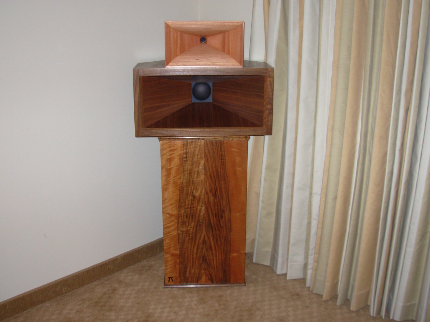
Constant directivity cornerhorns are even better, of course. But then again, like so many have said, they only really work in rooms with the layout. They have a midhorn and woofer blended in the 100Hz - 250Hz range to smooth the verical modes. And being acoustically close to both adjacent walls, there is no back wall or side wall reflection to smooth. The woofer isn't visible, it's facing the corner with large slots on the side for sound. The midhorn is just a few inches from the corner too. The tweeter isn't acoustically close, but it is directional, with less vertical spread to help reduce ceiling slap at HF. Here is a constant directivity cornerhorn at the same show, from a few years back:
Had you ever considered making a 2.5 way floor standing version of the design on stands ? If you extended the cabinet all the way to the floor, increased the width and depth slightly, it shouldn't be too hard to get nearly twice the internal volume.
No, I haven't. But I have suggested that very thing numerous times to DIYers, for the exact reasons you and I have been discussing. In my way of thinking, a 2.5-way speaker has a built-in flanking sub.
But my no-compromise solution is the constant directivity cornerhorn, for reasons described earlier in this thread and elsewhere. It pretty much solves all the problems - no side wall bounce because the sound sources are acoustically close and blending for the verticals.
Or do you think the flanking subwoofers which are displaced in all three axes is still a better approach overall ?
That's true, and is why I prefer the flanking sub approach to the 2.5-way. The 2.5-way is great, and if a person just has to have a single cabinet for WAF or whatever, I think it's excellent. But if you can separate the helper woofer, you can use it to smooth the notch from the wall behind the speakers, which is actually probably more important than floor bounce for stand-mounted two-ways.
My point is its only "problematic" if you stick to a 2 way constant directivity design. If that's what you like to design that's a trade off you might have to accept, but that doesn't mean there aren't other approaches where it's a non-issue, and rather easy to solve.
A more conventional 3 way design done properly can solve the problem for "free" just through appropriate choice of driver heights, crossover frequency, and network equalization.
Its also easy to hypothesize about what a design "might" do, but its not so easy when you actually have to build it and, God forbid, do it in a cost effective manner. I have looked at designs which are CD and have a narrower vertical polar pattern and they are not practical and have all kinds of other tradeoffs.
I don't follow the "floor - ceiling modal cancellation" and how any of this affects that - whatever it is. Sure there are floor to ceiling modes, but so what? There are all kinds of modes in a real room and remember the real room modes are never as nice looking as the ones that a computer draws. There are all knids of perturbations that make them anything but what a simple model will show.
In any case, I have a ceiling diffusor so thats also not an issue in my setup.
I like this graph/study from Dr. Olive about preferred room response curves:


Fixing the power response in the treble seems to have helped as did just 'fixing' it and the bass for just one location.
Thoughts?
Dan
Fixing the power response in the treble seems to have helped as did just 'fixing' it and the bass for just one location.
Thoughts?
Dan
What diffusor do you use? Something you made, or store bought? It's something I need to look into.In any case, I have a ceiling diffusor so thats also not an issue in my setup.
Then this is not a "small room". It takes a lot of open space for this to occur. That not the "assumption" that we are dealing with here.
Let's assume, for the sake of argument, a "medium" size room - perhaps a bit smaller than my room in New Orleans. Say 13 feet wide by 20 feet deep, with mancave privileges. I don't think it would be impractical to set speakers up 6 feet into the room, and thus have a > 10 ms bipole/dipole reflection path off the wall behind them. The distance of course would be much shorter to the side walls, but the combination of setup geometry and controlled directivity keeps the magnitude of any early-arrival sidewall reflection from the back of the speaker quite low in amplitude.
Edit: What I'm really most interested in is your assessment of the scenario I described in post 1268, assuming one can achieve the required setup geometry.
Duke
Last edited:
Let's assume, for the sake of argument, a "medium" size room - perhaps a bit smaller than my room in New Orleans. Say 13 feet wide by 20 feet deep, with mancave privileges. I don't think it would be impractical to set speakers up 6 feet into the room, and thus have a > 10 ms bipole/dipole reflection path off the wall behind them. The distance of course would be much shorter to the side walls, but the combination of setup geometry and controlled directivity keeps the magnitude of any early-arrival sidewall reflection from the back of the speaker quite low in amplitude.
I mentioned in an earlier post, I have 14 ms of delay from the dipole back wave in a room of only 8 feet wide and 19 feet long. I don't think it's an impractical set-up at all. The speakers take up very little room because they can be close to the side walls (in fact this keeps the stereo triangle sufficiently large in this case).
What diffusor do you use? Something you made, or store bought? It's something I need to look into.
I made it.
Linkwitz says he draws the line at 6mS, meaning the dipoles are at least 3 ft. out from any walls. Although more is definitely better, based on my own experience with my open baffle dipoles, I'd agree with Linkwitz's number as a minimum.
As far as distance out from the wall goes, Linkwitz's recommended minimum for a dipole is the same as my recommended minimum for a controlled-pattern bipole (measured to the center of the rear baffle). I think that three feet is about where the detriment from the increased < 10 ms reflection density begins to outweigh the benefit from the increased > 10 ms density, though individual preference would of course come into play. The subjective improvement from moving the speakers forward another two or three feet is surprisingly large, which supports the working theory here.
In my opinion the optimum pattern would be whatever best addresses the conflicting requirments of what's desirable in "early" (< 10 ms) reflections vs what's desirable in "late" (> 10 ms) reflections, and the best pattern for doing so may change from room to room. But in general, narrower patterns work better in smaller rooms.
Last edited:
- Status
- This old topic is closed. If you want to reopen this topic, contact a moderator using the "Report Post" button.
- Home
- Loudspeakers
- Multi-Way
- What is the ideal directivity pattern for stereo speakers?