I have posted some simulations of the Bliesma T34A in a waveguide designed for wide directivity to very high frequencies, and some renderings of possible cabinet configurations using the Purifi 6.5 Aluminium driver in some other threads.


I am now making a concerted effort to actually build something that I can listen to")
Finding time to finish the CNC I have been building (for a long time already) is proving hard and apart from aesthetics, I can make something simpler in appearance that performs pretty much as well with the already working tools I have. So a basic box with roundovers and a 3D printed removable waveguide will be the starting point.
Something more like this apart from the colour.

In case it is not obvious to anyone, I should mention that Ath from @mabat was used in the design process for the waveguide.
I am now making a concerted effort to actually build something that I can listen to
Finding time to finish the CNC I have been building (for a long time already) is proving hard and apart from aesthetics, I can make something simpler in appearance that performs pretty much as well with the already working tools I have. So a basic box with roundovers and a 3D printed removable waveguide will be the starting point.
Something more like this apart from the colour.
In case it is not obvious to anyone, I should mention that Ath from @mabat was used in the design process for the waveguide.
Last edited:
So far I have made a single waveguide that I am happy with the result of from the printer. This is made of eSun ABS+. PLA didn't actually print any nicer and the plastic is very stiff and brittle which I don't like. The ABS+ has a little bit of give to it and is much easier to remove the seam blemishes with a blade. I still need to dial in PETG to print better and I do like the material properties of Carbon Fibre PETG, but it has proven to be less reliable in printing without something causing a failure.


I have some other waveguides variants, (different CAD models and slicer settings) that I consider to be workable.

Many other variations and experiments were tried with varying degrees of success...

I have some other waveguides variants, (different CAD models and slicer settings) that I consider to be workable.
Many other variations and experiments were tried with varying degrees of success...
I checked the prices but they are quite high for the design as is. We'll see how it goes and if it works well enough I want to make it pretty.If you are happy with the wave guide design, maybe print a pair with MJF or SLS nylon?
Maybe both or a hybrid depending on the response. Crossover depends on the in box measurement but I imagine 1.5 to 1.8KActive or passive XO? What is the XO point you are planning?
The waveguide is pretty much the same size as the woofer, I have a T25B and M74P for a pod type idea.What about a total external tweeter pod?
CTC will be quite high because of the waveguide size but I don't consider that a deteriment.The woofer would sit on the very side (corner) of the box, of course, to keep cTc distance. I guess that the top baffle needs to be inclined, coz' you know, woofers need to breathe!
Since you have a CNC on its way, I don’t suppose you’ve considered designing a WG that was integrated into the baffle?
A version with the 4” or 5.25” mid-woofer in a cabinet made with Corian, HI-MACS or other synthetic stone or solid aluminium in an array of Candy-like Colours would be gorgeous but pack a powerful punch.
I know a guy with some PTT drivers that he could loan you…
Move over 🍏
A version with the 4” or 5.25” mid-woofer in a cabinet made with Corian, HI-MACS or other synthetic stone or solid aluminium in an array of Candy-like Colours would be gorgeous but pack a powerful punch.
I know a guy with some PTT drivers that he could loan you…
Move over 🍏
The renders in the first post are just for that purpose, but for now I have to decide between making a tool or making a speakerSince you have a CNC on its way, I don’t suppose you’ve considered designing a WG that was integrated into the baffle?
A version in with the 4” mid-woofer in a cabinet made with Corian, HI-MACS or other synthetic stone or solid aluminium in an array of Candy-like Colours would be gorgeous.
If I wanted to make something to sell that would probably be a good idea
A kind offer, I have many years worth of drivers to find a use for already though...I know a guy with some 4” PTT (or 8”) drivers that he could loan you…
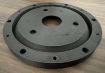
I've had some better sucess printing with PETG-CF, the top layer is very smooth and the outside walls look nice with the carbon material. The scuffs are from removing the random seam blobs. I'm not sure that I will be able to produce one of these waveguides with a finish I would be happy with straight off the printer. Printing in this orientation does not hide the layer lines well unless they are very thin, which presents print time and adhesion issues. This one stayed flatter than the ABS+. The pitch is higher with a knuckle test, definately stiffer than the ABS+, but not as brittle as PLA.
Attachments
So far I have made a single waveguide that I am happy with the result of from the printer. This is made of eSun ABS+. PLA didn't actually print any nicer and the plastic is very stiff and brittle which I don't like. The ABS+ has a little bit of give to it and is much easier to remove the seam blemishes with a blade. I still need to dial in PETG to print better and I do like the material properties of Carbon Fibre PETG, but it has proven to be less reliable in printing without something causing a failure.
View attachment 1320331
View attachment 1320330
You might want to try and smooth the ABS print with Acetone.
First guides found in a quick search:
https://www.wevolver.com/article/petg-adhesion
https://all3dp.com/2/abs-acetone-smoothing-3d-print-vapor-smoothing/
It doesn't work with PLA though, and I don't have a clue what to use for PETG
Thanks for the idea, I have seen a lot of those videos and I don't really like the melted look. It also concerns me that the dimensions will alter a little.You might want to try and smooth the ABS print with Acetone.
I was hoping the carbon filled filament would produce the stippled look, more like SLA resin but it doesn't happen in the waveguide profile. The layers need to be really thin to stop the outer part of the profile from suffering the same sort of issue that is often seen on the top of printed sphers. If the layer height is fixed the top gets quite rough.
All can be fixed with filler of some kind and sandpaper justs takes time and effort. UV resin and baby powder seems fast and smooth, I'm going to try plastic wood maybe thinned with acetone and brushed on. That seems quite popular in America with spot putty.
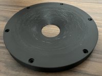
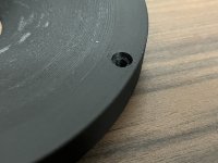
I have persisted with the PETF-CF filament and I was able to print it at quite small layer heights which has helped, apart from the seam which is impossible to hide completely and one line where something went slighty wrong, I think this is a nice result. A bonus of the PETG is that it stays very flat. This one is on a glass plate and there is no movement.

This one has bigger mounting holes to put heat set inserts in.

I have also printed some vibration damping squash ball feet to try out on the printer. Very nice fit and the print looks really good. I have two more new filaments to try out from QIDI, ABS Rapido and ABS-GF25 that has 25% Glass Fibre in it. Supposedly very strong and doesn't warp. Relatively expensive but not as bad as Nylon CF.

This one has bigger mounting holes to put heat set inserts in.
I have also printed some vibration damping squash ball feet to try out on the printer. Very nice fit and the print looks really good. I have two more new filaments to try out from QIDI, ABS Rapido and ABS-GF25 that has 25% Glass Fibre in it. Supposedly very strong and doesn't warp. Relatively expensive but not as bad as Nylon CF.
Last edited:
You seem to know more about 3D printing than me, but I had the same seam problem and someone pointed out a solution (and it did work for me). I use Ultimaker Cura but I know some other programs have something similar. In Cura it you set "z seam alignment" to "random". I don't actually have this visible in my print settings in the "Walls" section, but if I go to the search bar and type it in, it brings up the settings and I was able to select random from a drop-down menu. Not sure if this will solve your problem, but hope it is helpful..... apart from the seam which is impossible to hide completely ...
"
Thanks for the thought. In post #10 that print used random seam and the blobs were quite obvious. I removed them with a blade but it scuffed up the PETG CF in an ugly way. That one had thicker layers overall so I might try random again with the thinner layers. I did do that one one of the ABS test prints with thin layers and you couldn't really see it. It is interesting that the visually obvious seam feels smoother than the less visually obvious random seam. I somehow doubt that I will be happy with the look of any waveguide straight off the printer, but the last one would not require a lot of work to make it paint ready.I had the same seam problem and someone pointed out a solution (and it did work for me).
If I like the sound of the speaker I might try my hand at forged carbon, which I think looks cool
Not bad! I'd live with that in a finished speaker. I have the T34A's here, I'd be keen to follow along if you want to sell me a couple waveguidesI have persisted with the PETF-CF filament and I was able to print it at quite small layer heights which has helped, apart from the seam which is impossible to hide completely and one line where something went slighty wrong, I think this is a nice result. A bonus of the PETG is that it stays very flat. This one is on a glass plate and there is no movement.
View attachment 1322646
Off toppic - for vibratoin dampening get sylomer pads! They come in defined stiffness and you can chose the right one for the weight - from very light of just a few kg to pretty heavy. For sure better decoupling like any squash/tennis/whatever ball cause they are build for exactly that purpose.I have also printed some vibration damping squash ball feet to try out on the printer.
In Europe you get them ready cut in small round pads for about €15,- / 8 pcs on Amazon.
- Home
- Loudspeakers
- Multi-Way
- Wide Directivity 2 way compact Speaker T34A Waveguide and Purifi 6.5 Aluminium