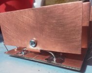
Thanks. Yes, short leads and board vertical mounted as trobbins suggested . The leads are short enough - 1/2 inch. Still the board pads are warm whilst the cases heatsinks are hot...
Maybe the zener case have propreties to conduct heat effective, They stated is made from "Void free, transfer−molded, thermosetting plastic" whatever it mean...
Maybe the zener case have propreties to conduct heat effective, They stated is made from "Void free, transfer−molded, thermosetting plastic" whatever it mean...
Last edited:
Perhaps try and appreciate the difference between thermal conduction in a metal, versus a plastic. The metal leads on either side of the zener are the lowest thermal resistance path for heat to take, as the leads but up internally to the pn junction where the heat is generated. The shorter the distance between package and solder joint the better. Imho, solder the entire length of each zener lead to the copper pad, to enhance the distribution of heat to the total pad.
Then, something is wrong. The leads now are pretty short 1/2 inch and are soldered to the both copper sides of the board. Still as I said the board pads are cooler than the case heatsinks. I don't know how much but I can keep the fingers on the pads for undetermined period whilst on the case heatsinks I cannot keep it more than 2 sec. (I ordered a temperature probe as necessary tools for this kind of tests). The Zener leads are generous soldered to the pads but not bended underneath (are already cut short). In this conditions I cannot imagine nothing but the solder should be responsable for a weak heat transfer. I used regular Stanol SnPb 40/60...🤔


Last edited:
Perhaps look again at Fig 32 of the Motorola link. 1/2" leads provide about 11C/W resistance to Tj. If Tj is dissipating 2W then lead has about 22C drop along its length - that is sort of the difference you are seeing when you touch the copper pad which is circa 22C below the junction temp.
If you reduce lead length to say 1/8" then the junction is only 6C above copper pad. It's not quite ideal like that, but the copper pad will end up hotter, and the junction will end up cooler, which is what you want.
I can see you don't want to give up on the custom package heatsinks you've spent time on, but imho its not a great way to continue.
What’s wrong with a MOSFET follower, see diagram
You can choose Rz a lot higher than the series resistor you have to use now.
Regards, Gerrit

You can choose Rz a lot higher than the series resistor you have to use now.
Regards, Gerrit
I can see you don't want to give up on the custom package heatsinks you've spent time on, but imho its not a great way to continue.
I fully agree by general principle (#148)...except the plastic mold is not somehow optimized for heat flow...(but didn't found any references...🫣 . I was against to use it till I did the test...and seems it is effective. Please give me a reason to not use it as I didn't see any as time is work...because I don't see any. Is not so effective as the leads heat transfer but I think is more than nothing. There are any bad consideration ...like thermal inertia or something else please? I asked as my previous test on a reference diode shows 33.8V without sink and 32.2V with it on case. For me was enough to conclude the diode work cooler with it...but who knows...it was an other user here who suggested the same (#149). I gaved him credit to do a test and was confirmed it work. Can You enlight me please ?Thanks.
Last edited:
Maintenance and access to each heatsink clamp on each diode is one concern. I'd suspect a slightly higher thermal resistance with your existing setup, but that would require a 1:1 comparison.
Post #149 refers to a heatsink for a 14-16pin DIP. The heatsink datasheet does not provide an Rth from DIP device Tj to DIP surface (typically referred to as Tjc), which may be significant compared to that heatsink's 65C/W for free air (you may not have appreciated how high the thermal resistance of that heatsink was for free air).
Post #149 refers to a heatsink for a 14-16pin DIP. The heatsink datasheet does not provide an Rth from DIP device Tj to DIP surface (typically referred to as Tjc), which may be significant compared to that heatsink's 65C/W for free air (you may not have appreciated how high the thermal resistance of that heatsink was for free air).
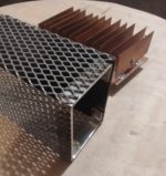
I figured a protection 'case' for the unit, included series resistors, on a FR4 board. It is completely transparent for air flow and will be mounted in the back of chassis , like an extension ( it have same hight ). Actually the current is more 75-80mA after tweaking. It is not perfectly stable, the voltage fluctuation from iddling to max is ca. 15V (less than 5 percent). We have to consider the PT also sag a bit ca.10Vdc after 1st power cap...still, so the fluctuation may be a consequence.A 25W transistor heat sink won’t be any smaller, but it will be more convenient to work with. If you use a fullpack encapsulated TO-220 and heat shrink on the leads you wont have to worry about high voltages and user’s fingers. Can’t mount that zener monstrosity anywhere it might come in contact with people or pets (Which means INSIDE the enclosure, where air circulation is limited).
You will also only be pulling 65 mA peak, not 65 mA all the time.

Last edited:
It is a vicious circle : draw some amount of current getting heat, getting heat it have a drift voltage. It cooling more get lower voltage who allowed more current to draw and in consequence get more heat again. Never end it. The norm power vs current meant nothing from a real application point. Power vs temperature is more realistic. ...what about cooling in liquid nitrogen ?...I think they may rate this diode at 50w or so...Well if you rate the device in term of temperature how the temperature condition may be assured as time there are not provided ways to cool it, other than the leads (with a limited capacity to handle heat transfer ) ? I was well adviced to use the sand as warm to may keep comfortable a finger on it...That mean half of watt or so...A 5w device is supposed to be a power device, using for 1w seems a joke...
Last edited:
A 200 watt TO-3 power transistor may only be good for 40 watts of average heat dissipation on a practical heat sink. TO-220’s are only good for about 20, despite “dissipation ratings” approaching the TO-3. It seems that diodes are no different. Want more? Forced air. Then you’ve got to put up with the racket a fan makes.
Imho you need to appreciate how to derate component operation - that requires a good understanding of electronics and how to interpret datasheet details and associated aspects like thermal dissipation. It is naive to call something a joke as it shows a lack of understanding.
Perhaps go back to why you think you need to drop voltage, then look at the option of using a choke input configuration for screen supply.
Perhaps go back to why you think you need to drop voltage, then look at the option of using a choke input configuration for screen supply.
Yes exactly what I said: Why not 50W if nitrogen cooling is an option ? Is a banal tht diode , a trough the hole component supposed to be mounted on a top of a pcb in an 25 Celsius degree environment.
I have a 25 C environment and a PCB with two holes on it and a diode which is supposed to dissipate by themselves...These are the conditions the diode was designed to be used by normal application...if have no pretend to dissipate more than 0.5W. The rest are derating conditions, not normal conditions by intended application.
I have a 25 C environment and a PCB with two holes on it and a diode which is supposed to dissipate by themselves...These are the conditions the diode was designed to be used by normal application...if have no pretend to dissipate more than 0.5W. The rest are derating conditions, not normal conditions by intended application.
Last edited:
For sure those heatsinks improvisation I did are not...There is no way to cool the leads at 3/8 inch at 25Celsius degree as they claims in test whilst dissipate over 2W from natural convection...maybe max 0.5-1W maybe
A power transistor is supposed to be mounted on a heatsink. Those 5w diodes not. Is not a matter of datasheet understanding. Is as simple after couple of tests using those diode at say 2W is not feasible because there are not decent practical solution to do. So a 5w rating is a joke from my point.
A power transistor is supposed to be mounted on a heatsink. Those 5w diodes not. Is not a matter of datasheet understanding. Is as simple after couple of tests using those diode at say 2W is not feasible because there are not decent practical solution to do. So a 5w rating is a joke from my point.
Last edited:
2W from natural convection would probably put Tj at the 200C Si limit. The case could be hot enough to burn flesh. If you were only using ONE, and it was mounted to a .062 FR4 with 4 square inches of 2 oz Cu on each end it might be good for a couple watts reliably. That would be a typical power supply application. They can also tolerate much higher non repetitive surge currents than one watters, in applications where they suppress transients.
I don’t think they had tube amp shunt regulators in mind when they made these.
I don’t think they had tube amp shunt regulators in mind when they made these.
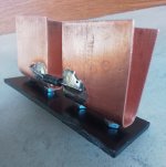
Thanks. You mentioned about 4 square inch of laminated copper on pcb at each side. A 2 square inch heatsink will be enough ? I meant an "U" shape of 2 square inch total at each end soldered with extremely short leads...
I figured one for a test. A bit over 2 square inch per side. Should it work please ?2W from natural convection would probably put Tj at the 200C Si limit. The case could be hot enough to burn flesh. If you were only using ONE, and it was mounted to a .062 FR4 with 4 square inches of 2 oz Cu on each end it might be good for a couple watts reliably. That would be a typical power supply application. They can also tolerate much higher non repetitive surge currents than one watters, in applications where they suppress transients.
I don’t think they had tube amp shunt regulators in mind when they made these.

I did a comparative test measuring the temperature of the leads in very proximity of the case as follow:Fire it up and see how hot it gets.
For initial jig with pcb pads and case heatsink I got 75*C (167*F) and 32.05V
For 'U' shaped heatsink I got 55*C (131*F) and 31.7V
As the mains voltage was shifting, now the current draw is 80mA. I measured in same conditions on the leads in very proximity of the case and got 85 C (185 F) on first version and 65 C (149 F) on 'U' shaped. Voltage 31.9V 80mA, 2.56W around. It is safe at 149*F at the end of the case please ?
- Home
- Amplifiers
- Tubes / Valves
- Williamson first stage question