A few people have asked about wiring up a dual mono amp. There are separate power supplies and lots of opportunity for cross channel ground loops and ordinary 'classic' ground loops as well.
Here is a scheme that should allow a dual mono amp to be wired up that is quiet - ie no hum.
The trick it to ensure that there is one and only one connection between the two amplifiers, and that is accomplished by bonding the input connector signal grounds together.
The wiring scheme uses two ground lifters, although you could cheat and just lift one of the amps, and ground the other directly to the chassis, but I suggest you just spend a little extra effort and use two ground lifters.
A major issue here, as in any DIY amp, is safety. Kindly note the chassis (assumed to be steel or aluminium) is bonded directly to the incoming safety ground (earth) on the IEC receptacle. You cannot under any circumstances omit this connection - it is the most important connection in any amplifier. Using the ground lifters, the two amplifiers and their associated power supplies 0V then float +- 1.4V around the safety ground (earth). For the ground lifters, I always recommend you use a decent 35A 400V bridge rectifier - details in the presentation.
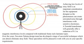
For the transformers, use a Toroidy (based in Poland) audio grade device with a GOSS band to minimize the radiated mag field, or if specifying custom devices, ensure your order your transformer with a GOSS band. An interwinding screen will also help to minimize mains conducted common mode noise.
One final point: do not mount your input RCA connectors on opposite sides of the rear panel. Mount them next to each other in order to minimize the inter-channel loop areas - again, details in the presentation.
")
Here is a scheme that should allow a dual mono amp to be wired up that is quiet - ie no hum.
The trick it to ensure that there is one and only one connection between the two amplifiers, and that is accomplished by bonding the input connector signal grounds together.
The wiring scheme uses two ground lifters, although you could cheat and just lift one of the amps, and ground the other directly to the chassis, but I suggest you just spend a little extra effort and use two ground lifters.
A major issue here, as in any DIY amp, is safety. Kindly note the chassis (assumed to be steel or aluminium) is bonded directly to the incoming safety ground (earth) on the IEC receptacle. You cannot under any circumstances omit this connection - it is the most important connection in any amplifier. Using the ground lifters, the two amplifiers and their associated power supplies 0V then float +- 1.4V around the safety ground (earth). For the ground lifters, I always recommend you use a decent 35A 400V bridge rectifier - details in the presentation.
For the transformers, use a Toroidy (based in Poland) audio grade device with a GOSS band to minimize the radiated mag field, or if specifying custom devices, ensure your order your transformer with a GOSS band. An interwinding screen will also help to minimize mains conducted common mode noise.
One final point: do not mount your input RCA connectors on opposite sides of the rear panel. Mount them next to each other in order to minimize the inter-channel loop areas - again, details in the presentation.
Attachments
Last edited:
Ground lifters are not required if wired correctly and all grounds are returned to the same point.
You state "GOSS" band.
That is actually a Gauss band, a simple copper or non ferrous material covering the windings. Very popular with the Chinese.
Does nothing apart from making the transformer look nice and covers up the windings.
You state "GOSS" band.
That is actually a Gauss band, a simple copper or non ferrous material covering the windings. Very popular with the Chinese.
Does nothing apart from making the transformer look nice and covers up the windings.
This is an interesting topic.
What if you do not connect the input grounds ("true" dual mono in one cabinet)?
I doing like You mentioned. Inputs are separated from each other. Ground lifter use DRC network. This solution works fine.
Sajti
The reason for bonding the grounds together is to trap any cross channel loop currents (signal and mains related) in the amplifier. If you have a good layout and do not bond the inputs you may have a quiet amplifier, but bonding them (and the RFI cap) makes it foolproof. You do not want any mag fields generated in the amp generating an emf that then causes current to flow in the interconnect.
The ground lifters in the example posted keep the amplifier modules electrically separated as well.
The ground lifters in the example posted keep the amplifier modules electrically separated as well.
Last edited:
For quite some time I've been thinking about a ground scheme for any amplifier that uses a mains transformer with an inter-winding shield:
What if the chassis and the inter-winding shield are connected to safety earth, but the transformer secondaries and none of the audio circuitry are?
So the audio ground would be floating (could be HF connected to chassis nonetheless), but safety should be ensured because in case of an accidental short of the mains to the chassis, the circuit breaker would trip. Likewise, in case the transformer primary insulation fails, the grounded inter-winding shield makes the circuit breaker trip.
Does it make sense from a technical point of view?
Would this be legal?
I have remarked elsewhere that building double insulated gear as a DIY’er is not possible. Not for any other reason than this type of gear is for the most part certified for safety reasons.
For DIY gear, best safety practice says the incoming earth (safety ground) is connected directly to the metal chassis and all metal parts are in contact so no part of the chassis is floating, and the amplifier 0V is also connected to the chassis. If at any point mains gets onto the chassis (eg transformer fail, or a wire fail in the amp, or externally mains ends up on the chassis), it remains safe and the RCD (aka GFI) will trip.
If you foolishly decide not to follow best practice then of course it’s easy to break ground loops.
FYI one of the worst examples of this is on the Taylor Guitar Amplifiers on YouTube where the guy uses a grounding plug to break the safety earth. The hum goes away, but the amplifier is as a result unsafe (there’s a link to the video on the Ground Loops page on my website).
So, the correct approach is to make sure the amp is safe, and there is no hum.
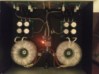
I usually keep the wire length as short as possible. From the RCA to the amp PCB is 10cm. From the amp pcb to the output is 14cm. From the psu to the amp pcb is 5cm...
This has some restriction to keep the amplifier pcbs on the back wall of the amplifier box.
Sajti
Sajti, how does this minimize the cross channel ground loop if the grounds are joined back at the source (talking here about unbal interconnects)?
Sajti, how does this minimize the cross channel ground loop if the grounds are joined back at the source (talking here about unbal interconnects)?
Frankly speaking, I never thinking about it. This configuration was developed during practice. Anyway I use 100ohms ground loop breaker resistors for each channel.
Sajti
The reason for bonding the grounds together is to trap any cross channel loop currents (signal and mains related) in the amplifier. ...
Thought experiment :
- two independent "mono blocks"
- will be moved close together
- then fixed on a common metal plate
- finally their respective inner sides removed so to become a dual mono amp.
At which point will you move the inputs in close proximity and connect their grounds ?
Frankly speaking, I never thinking about it. This configuration was developed during practice. Anyway I use 100ohms ground loop breaker resistors for each channel.
Sajti
If you have a good technique and you are getting low noise, then that’s great.
(What noise levels are you getting wrt to 0 dBV? )
If you have a good technique and you are getting low noise, then that’s great.
(What noise levels are you getting wrt to 0 dBV? )
It is hard to measure, but something like -95dB ref. 1W. Shorted input.
Sajti
Ground lifters are not required if wired correctly and all grounds are returned to the same point.
You state "GOSS" band.
That is actually a Gauss band, a simple copper or non ferrous material covering the windings. Very popular with the Chinese.
Does nothing apart from making the transformer look nice and covers up the windings.
FYI.
Source: Nuova Talema
Attachments
“ One final point: do not mount your input RCA connectors on opposite sides of the rear panel. Mount them next to each other in order to minimize the inter-channel loop areas - again, details in the presentation.”
Ok, let’s think for a minute about this one; is it where the RCAs are mounted, or maybe the distance between the circuits that are prone?
After all, a loop doesn’t care about whether the RCA jack itself is located if the distance between the amp boards is the same either way, right?
No easy way with this one, have tried many different schemes.
Maybe you can get to -105 dBV
Maybe. But I can hear some white noise only if i put my ears 1cm close to the speaker.
Anyway my future plan is to make real monoblocks.
Sajti
Attachments
Last edited:
“ One final point: do not mount your input RCA connectors on opposite sides of the rear panel. Mount them next to each other in order to minimize the inter-channel loop areas - again, details in the presentation.”
Ok, let’s think for a minute about this one; is it where the RCAs are mounted, or maybe the distance between the circuits that are prone?
After all, a loop doesn’t care about whether the RCA jack itself is located if the distance between the amp boards is the same either way, right?
No easy way with this one, have tried many different schemes.
The shortest path between the connectors and the amplifiers is not necessarily the one that minimizes noise. . See how the input cables are routed on slide no. 4. If the input connectors were on opposite sides of the rear panel and the internal wiring going straight to the module, you have a very large loop area.
It looks counter- intuitive but it gives the least loop area compared to just running the cable to the amp modules with the input connectors located on opposite sides of the rear panel. The transformers (even with a GOSS band) will be radiating an EM field this will generate an EMF between the left and right channels that will flow in the screens, degrading noise. (Important also to install a hum breaking resistor on the amp modules to reduce this current).
Last edited:
Bonsai,
Thanks for the invite!
What practical differences in wiring would there be if an XLR input is used with balanced to SE conversion? I used to use transformers but find modern opamp designs much to my liking such as:
AMB’s Alpha 24
Neurochrome’s THAT Rx and Universal Buffer designs
XRK’s BTSB
I have simplified my physical chassis requirements by primarily using toroid transformers with (4) secondary pairings for a dual mono build but without the physical constraints and encumbrances of having 2 donuts in the chassis.
Thanks for the practical presentation; tremendously useful for diy’ers.
Best,
Anand.
- Home
- Amplifiers
- Solid State
- Wiring Up Dual Mono Amplifier