@bonsai
What I'm considering is a kind of mashup of Marsh, Galo, Colborne and maybe Evans. I'm trying to rationalize the grounding between these where there is a transformer secondary for each polarity/channel (no centre taps) and separate grounds run for signal and power (see Marsh's headphone board) 6L6 drew a grounding scheme for the Pearl 2 that echos your bridge-connected grounding but eschews the shielding efforts at the input jacks.
Also, I wondered if you had an opinion on the pseudo Faraday cage that Tom Evans chose for the Groove. Could that work? Thanks!
Attachments
It looks counter- intuitive.
I should have actually looked at your diagram before assuming like I had, just have seen so many over simplified explanations for these problems...
And what if the input is switchable RCA-XLR ?
The trick is to ensure that there is one and only one connection between the two amplifiers, and that is accomplished by bonding the input connector signal grounds together.
One final point: do not mount your input RCA connectors on opposite sides of the rear panel. Mount them next to each other in order to minimize the inter-channel loop areas - again, details in the presentation.
I am sure Bonsai has a more thorough explanation but I imagine since you are still selectively using an RCA source when needed, there will be a chance of a ground loop to occur as such you will have to mount the RCA’s (and consequently the XLR’s) close together to minimize the interchannel loop area.
Best,
Anand.
Last edited:
Yes for standard stereo power amps. There will be a learning curve and I have not got around to this. The technique is something like binding the L &R inputs together, then taking them across to the speaker -ve, bonding those together, and then bonding that to the PSU 0V. All the bonds have to be short and thick.
This approach still requires that the internal loop areas are kept as small as possible.
This approach still requires that the internal loop areas are kept as small as possible.
@bonsai
What I'm considering is a kind of mashup of Marsh, Galo, Colborne and maybe Evans. I'm trying to rationalize the grounding between these where there is a transformer secondary for each polarity/channel (no centre taps) and separate grounds run for signal and power (see Marsh's headphone board) 6L6 drew a grounding scheme for the Pearl 2 that echos your bridge-connected grounding but eschews the shielding efforts at the input jacks.
Also, I wondered if you had an opinion on the pseudo Faraday cage that Tom Evans chose for the Groove. Could that work? Thanks!
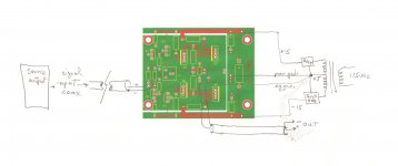
I’m not an expert in these things, but can only give an opinion. If you separate the PSU from the RIAA preamp part, that’s a good move in terms of reducing any mag field coupling to the electronics. Just make sure the supply cables between the two boxes are tightly bound together. You could use a 5 pin XLR interconnect for this purpose. Connect the screen one end, and tie the other end of the screen to the other box through a 2-5 nF ceramic cap. This will provide RFI screening. Use the internal cables to carry the +- and 0 V between the two housings. You could put a switch across the ground lifter. I did this on my X-Altra MC/MM preamp and found I did not need the GL - but the option is there to easily flip between the two.
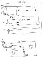
The grounding scheme as drawn looks good - no loops. The devil is in the detail though, so the PCB layouts will still need to keep loop areas small and grounding on the boards has to avoid common impedance coupling.
I see you only show one input and one output - I assume you will you have two of those boards in the preamplifier housing? If so, make sure there is only a single common bond point to which the PCB 0 V, the incoming PSU 0 V and the housing all join ie star ground.
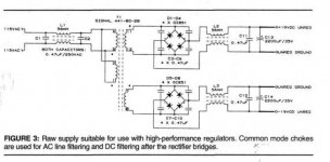
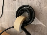
For the PSU, I have never used common mode chokes in the secondary’s - maybe someone can comment on this. All my PSU’s simply rectify, smooth and go straight to regulators. I use common mode toroidal chokes on the mains cable to kill common mode RFI. This just consists of passing the mains cable through the toroid 4 or 5 times. I’ll post a picture a bit later.
For the caps across the bridge rectifiers, see Mark Johnson’s diode switching noise write up for the best solution.
Re the pseudo Faraday cage. Screening like this only works at RF frequencies (and I am not sure quite how well) and will have no effect at mains frequencies. There is a lot of literature on this subject to this end.
But, since the preamp is already enclosed in a metal housing, I don’t know what additional value this brings to be honest.
But, since the preamp is already enclosed in a metal housing, I don’t know what additional value this brings to be honest.
@bonsai
Thanks for all that. I'll have to sit down and digest it all.
One question: If I star ground in the signal box since there is no corresponding ground on the secondary side in the PSU do I run a separate ground conductor back to the safety ground point via a bridge there too?
Re the Evans Groove, his signal cases are acrylic. His designs have been reviewed as being dead quiet though that was generally attributed to his "super" regulation design not the cage.
For the grounding thing, because the wiring is in separate boxes, I don't think you need a separate safety ground (earth) on the amplifier box - only on the power supply box.
Re the Tom Evans phono amp, I heard they were quiet, but the Faraday shield would offer no protection against mains and LF mag fields. Same as the screen on a screened cable - almost all of the rejection of LF and mains comes from the fact that the loop area between the screen and the inner core wires is very small - so the magnetic field coupling is therefore weak. At RF, its a different story where the coupling is through the electric field (couples easily via capacitance), and here the screen acts as a Faraday cage so that any RF impinging on the screen causes a current to flow in it which we can then shunt away from the input circuit and to the housing using for example the previously mentioned 2-5 nF disc ceramic cap. The RFI is almost always common mode and if you allow this to get into the electronics, it gets demodulated and you can hear AM radio.
To be useful at RFI, the complete circuit must be enclosed in the Faraday shield - this is the reason for my earlier comments BTW wrt screening the power cables between the PSU box and the RIAA amplifier box. If you look at equipment where RFI is a problem (eg sensitive RF analyzers or generators), the housings use special finger contacts between thew various parts of the conductive housing to ensure the internals are completely encased, and this is sometimes even carried through to the internal modules etc.
You can build a very quiet amplifier in a plastic box, but there will be no protection from mag fields. The only way you can minimize this is to keep the loop areas in the circuit as small as possible and separate the PSU as in the Tom Evans design is a good way to do this. Also, you will have to keep any other mains cabling well away from the amplifier box.
Last edited:
For RFI problems, this is the best document I have found
http://www.audiosystemsgroup.com/RFI-Ham.pdf
http://www.audiosystemsgroup.com/RFI-Ham.pdf

Whatever approach you use, keep the ground and input signal (L and R) tightly bound together to minimize loop area.
what about the amp circuitry and output cables? (i am echoing what was mentioned in post 17)
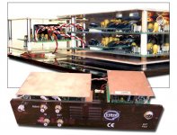
Here is the picture of the common mode choke on a phono input that kills RFI. This trick is straight out of the Jim Brown article I linked to in post #52. I can attest to the fact that it works extremely well.
Attachments
Last edited:
what about the amp circuitry and output cables? (i am echoing what was mentioned in post 17)
Usually less of an issue on the speaker output cables in my experience, but you should still minimize loop areas - most speaker cables do this anyway.
Inside the amp, all loop areas should be minimized- PSU, PCB layout, internal wiring.
Bonsai,
In the link below, I figure the capacitor/thermistor (C23/TH1) combination should be enough as a ground loop breaker yes? Or do I have to add an additional rectifier as you have mentioned in your document?
https://www.diyaudio.com/forums/gro...-mx-class-power-supply-gb-14.html#post5782064
Thanks,
Anand.
- Home
- Amplifiers
- Solid State
- Wiring Up Dual Mono Amplifier