Capacitor Substitutions
X, You've got me thinking about laying larger caps on their sides... Not just the power rail caps, but also the output caps. I'm building two of these, and I want at least one to be compatible with low impedance cans. I may even give one away to my friend with 25 ohm Grados, and I want the bass to thump.
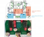
I am looking at these caps: Nichicon UKA "High Grade Audio" series. I could fit 647-UKA1E102MPD 1000uF for output caps and UKA1E471MPD 470uF for the power rail caps (not quite the 22K you used X, but its the biggest that will fit along with larger output caps). Here's a mock-up image of what the arrangement would look like.
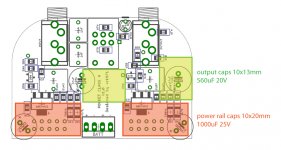
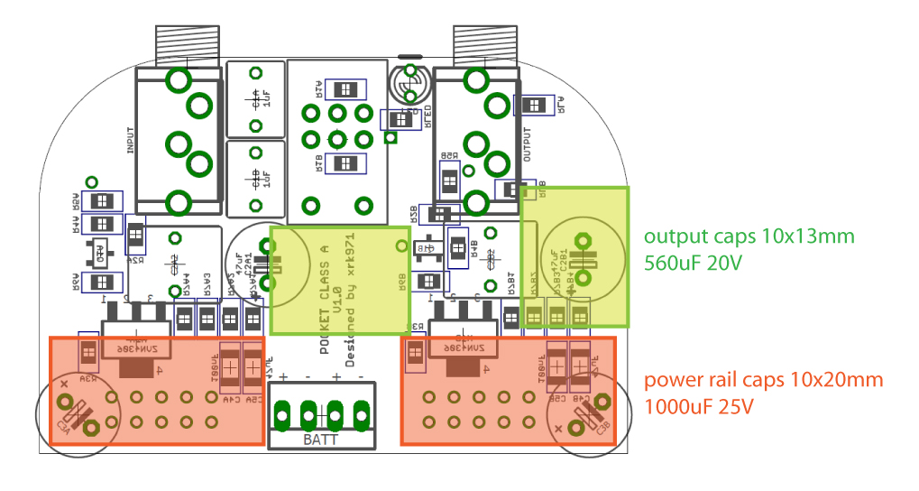
As an alternative option for power rail caps, I found a larger Panasonic polymer cap, P16316-ND, which is 560 uF, and might *just barely fit (10 mm x 13 mm) in the remaining space, if I'm lucky.
Anybody have experience with these newer Nichicon UKA caps?
And please, any opinions on Nichicon 470uF electro VS. Panasonic 560uF poly for power rail caps? I have no experience with any of them so I'm open to suggestions.
Just a note to folks still getting BOM. It's ok to use as large of a cap as you can fit for the corner mounted power rail caps. A larger value gives better stereo crosstalk reduction. I am able to fit 10mm dia x 20mm long 2200uF 16v caps laying on their sides. There is an improvement in imaging, maybe a bit better bass authority as well. Yes, 16v is marginal but a pair of 9v rechargeable Li-ion batteries is 16.7v max and that drops quickly below 16v within 30min of use. If you use alkaline 9v cells I suggest getting a 20v (smaller cap) though.
X, You've got me thinking about laying larger caps on their sides... Not just the power rail caps, but also the output caps. I'm building two of these, and I want at least one to be compatible with low impedance cans. I may even give one away to my friend with 25 ohm Grados, and I want the bass to thump.
I am looking at these caps: Nichicon UKA "High Grade Audio" series. I could fit 647-UKA1E102MPD 1000uF for output caps and UKA1E471MPD 470uF for the power rail caps (not quite the 22K you used X, but its the biggest that will fit along with larger output caps). Here's a mock-up image of what the arrangement would look like.
As an alternative option for power rail caps, I found a larger Panasonic polymer cap, P16316-ND, which is 560 uF, and might *just barely fit (10 mm x 13 mm) in the remaining space, if I'm lucky.
Anybody have experience with these newer Nichicon UKA caps?
And please, any opinions on Nichicon 470uF electro VS. Panasonic 560uF poly for power rail caps? I have no experience with any of them so I'm open to suggestions.
Attachments
Nichicons are fine for power rail caps. If you can fit larger ones like 1000uF x 2 it will really help the stereo separation and eliminate the power-off thump. There wlll be power-on thump still and that is only avoidable with a dedicated delayed relay or do not plug phones in until after unit is turned on. I cheat by using lower voltage rating of 16v and take my chances but this allows me to fit 2200uF Nichicons (16v) which are 10mm dia x 20mm long as power rail caps.
1000uF output caps will give you 6.4Hz bottom end which is great. Cool that you can fit them there. But 470uF will get you about 13Hz which is pretty darn good.
1000uF output caps will give you 6.4Hz bottom end which is great. Cool that you can fit them there. But 470uF will get you about 13Hz which is pretty darn good.
Yeah I forgot to mention, but I think you noticed, that that I was trying to use all caps rated above 20v for no worries using alkaline batteries. What about the 560uF Panasonic P16316-ND poly cap I mentioned, for the power rail caps? Would be a squeeze but a bit more capacitance. What sounds better in general, those or the Nichicons?
Last edited:
After looking more closely at your post, I see you were suggesting that I consider swapping my proposed caps around from the way I drew it up. So 1000uF on for power rails and 470uF (possibly 560 OS-CON) for the output. Still respectable bass extension with better channel separation and less power-off thump. Nice.
If you can fit 1000uF all around even better.")
I don't think I can unless I drop cap ratings to 16V like you did.
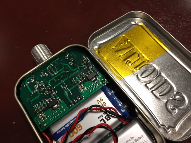
But, it will fit the way you mentioned, with the bigger caps on power rail duty! See pic attached at bottom.
I'm tempted to try this arrangement. You still think I'd be better off going with biggest possible 16V caps? Sorry if I am overthinking this...I just want to do your design the utmost justice!
BTW, look at what this guy rigged up to A/B audio capacitors! Me want...
From High End Audio - Electrolytic capacitors

Attachments
Last edited:
Nice arrangement! That's tight but just enough room. Make sure you put shrink wrap on long exposed leads. Also give power rail caps 1mm spacing so doesn't actually touch PCB (it's hot there). I think this will sound great. 16v caps will probably be safe for perhaps 20% of rating. Do this at your own risk though - worst case is it blows up like a firecracker. I am using Li-ion so 16.4v max is no big deal for 16v rating.
I have only had a cap blow up once because I put 44v by accident on a 20v one. Way over the rating. And it was a Big Bang like a firecracker.
Last edited:
330uF 25v SMT's are tiny
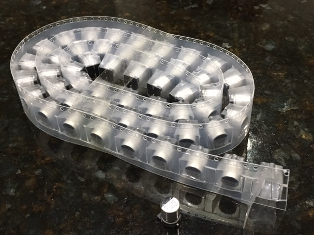
I just got a tape roll of qnty 50 x 330uF 25v "RVT" SMT electrolytics from Aliexpress for $6.50. These things are 7mm dia x 10mm tall. I think a future layout could have qnty 3 or 4 of these as outputs and when in parallel, the ESR could be even lower than a single OSCON. I measured the ESR at 120Hz and it was 0.7ohms (nothing to brag about) but 0.7/4 is 175mOhms and 1300uF in about the same size space as one of the larger 1000uF caps.
Although, my cheap JWCO 2200uF 16v caps measure in at 250mOhm at 120z - not too bad. Those are safe to use as outputs because the DC level there is circa 8v to 11v.
Attachments

Last edited:
So I went in on my Pocket class A amp and replaced my rail caps with 2200uF 16v "JWCO" brand caps. The turn off thump is gone, there is a turn on thump but it's not deadly. My DT880's survive it but it is recommended to not plug in the phones until after power up. Power off is no problem. The stereo crosstalk went from an Ok value of -52dB to a very respectable -74dB now. This is on a par with a state of the art opamp based headamp like Fiio A5 or Agdr's Super CMOY. Stereo imaging is improved.
I'll be interested to find out how those RVT caps in parallel work out.
8v to 11v at output? If this is true, then there is no reason to go place anything higher than a 16v cap there, correct? Glad you mentioned this. I'll poke around Mouser for another OSCON...maybe I'll fit 1000uF caps all around after all!
Also, I think I found a way to put a little space between the caps and the board. This guy uses double-sided foam tape, and he says it works out even near hot parts. I'll just put it on the side of the cap instead. From Capacitors | Tubelab

Although, my cheap JWCO 2200uF 16v caps measure in at 250mOhm at 120z - not too bad. Those are safe to use as outputs because the DC level there is circa 8v to 11v.
8v to 11v at output? If this is true, then there is no reason to go place anything higher than a 16v cap there, correct? Glad you mentioned this. I'll poke around Mouser for another OSCON...maybe I'll fit 1000uF caps all around after all!
Also, I think I found a way to put a little space between the caps and the board. This guy uses double-sided foam tape, and he says it works out even near hot parts. I'll just put it on the side of the cap instead. From Capacitors | Tubelab
Scotch extreme mounting tape might work even better:
http://a.co/blKuste
It's more 'rubbery' than the foam tape, and you can use a tiny piece as it's super strong.
No evidence that it holds up to heat better, other than I 'think' it would
http://a.co/blKuste
It's more 'rubbery' than the foam tape, and you can use a tiny piece as it's super strong.
No evidence that it holds up to heat better, other than I 'think' it would
I just create a gap with bent leads - seems to be strong enough to hold it in place.
Another trick for thermal management is to take a piece of Kapton tape and place it below the circuit board and above the circuit board mounted to the tin wall. The emissivity of shiny metal is about 0.2, placing tape on it makes surface about 0.9. So you increase your radiation heat transfer by 5x to help cool the amp better. A little trick they use on spacecraft radiators or when you need accurate temp of metal surface using IR camera. Even white paper masking tape works better than no tape. The Kapton is thinner and more thermally conductive so you get the best heat transfer. I do notice the amp feels cooler with the tape mod in place.
Another trick for thermal management is to take a piece of Kapton tape and place it below the circuit board and above the circuit board mounted to the tin wall. The emissivity of shiny metal is about 0.2, placing tape on it makes surface about 0.9. So you increase your radiation heat transfer by 5x to help cool the amp better. A little trick they use on spacecraft radiators or when you need accurate temp of metal surface using IR camera. Even white paper masking tape works better than no tape. The Kapton is thinner and more thermally conductive so you get the best heat transfer. I do notice the amp feels cooler with the tape mod in place.
Attachments

Last edited:
Now that we are getting close to building, I want to give some more info on the finer points to make this amp as good as possible. You can use randomly selected JFETs and MOSFETs and it will work and probably sound fine. If you want very good channel balance, you should try to match the JFETs at the operating condition. By matching at actual conditions (in-situ - in the actual amp) you will be guaranteed that the device is matched in both Idss and Vgs at the applicable condition.
So install all the SMT parts except the output MOSFET and the input JFET. Connect the two 9v battery power supply and solder a couple small wires across the 1k Drain resistor (R3). Take some alligator leads from your DVM and connect to those leads. Now monitor that voltage as you carefully place a BF862 onto the 3 pads and push down on it with a non-conductive push stick to make contact with the electrical pads. Note the voltage across R3 after 3 seconds record it and tape the tested BF862 next to the value. It will be of order 3v to 5v. That number is the steady state DC current (in mA) through the JFET at the exact operating condition. Instead of using your amp, you could etch a small test jig like I did. I bought a spool of 50 of these and find that within a dozen I can get 2 or 3 matches within 50 microamps or better than 2%.
Here is my dedicated JFET tester jig:
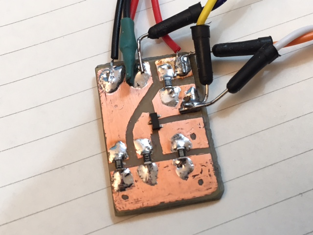
For the ZVN4306, you need to monitor the Source pin voltage realtive to ground (tpyically around 7 to 9v). After you solder your selected (and matched) BF862's in place, put the ZVN4306 DUT over the pads and push it down and read voltage after 3 seconds (be consistent but don't wait too long as it heats up). If you match this within 0.1v you will have a very balanced (left/right) system.
You can also use the Nelson Pass method to measure the Vgs:
http://www.diyaudio.com/forums/solid-state/299546-nelson-pass-easy-peasy-mosfet-vgs-measurement.html
You can also do it outside of the amp with something like this to get the Idss:
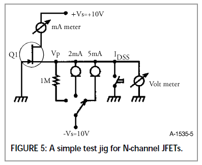
So install all the SMT parts except the output MOSFET and the input JFET. Connect the two 9v battery power supply and solder a couple small wires across the 1k Drain resistor (R3). Take some alligator leads from your DVM and connect to those leads. Now monitor that voltage as you carefully place a BF862 onto the 3 pads and push down on it with a non-conductive push stick to make contact with the electrical pads. Note the voltage across R3 after 3 seconds record it and tape the tested BF862 next to the value. It will be of order 3v to 5v. That number is the steady state DC current (in mA) through the JFET at the exact operating condition. Instead of using your amp, you could etch a small test jig like I did. I bought a spool of 50 of these and find that within a dozen I can get 2 or 3 matches within 50 microamps or better than 2%.
Here is my dedicated JFET tester jig:
For the ZVN4306, you need to monitor the Source pin voltage realtive to ground (tpyically around 7 to 9v). After you solder your selected (and matched) BF862's in place, put the ZVN4306 DUT over the pads and push it down and read voltage after 3 seconds (be consistent but don't wait too long as it heats up). If you match this within 0.1v you will have a very balanced (left/right) system.
You can also use the Nelson Pass method to measure the Vgs:
http://www.diyaudio.com/forums/solid-state/299546-nelson-pass-easy-peasy-mosfet-vgs-measurement.html
You can also do it outside of the amp with something like this to get the Idss:
Last edited:
Another trick for thermal management is to take a piece of Kapton tape and place it below the circuit board and above the circuit board mounted to the tin wall. The emissivity of shiny metal is about 0.2, placing tape on it makes surface about 0.9. So you increase your radiation heat transfer by 5x to help cool the amp better.
Neat. Following this logic, would painting the inside of the tin flat black cause the tin to absorb even more heat?
It depends on the paint. You want a special grade aerospace black paint called Z-93. But perhaps your regular Home Depot matte black paint can work fine. Anything is almost better than bare shiny metal. I know Kapton works very well and also acts as electrical insulator to prevent surfaces from causing shorts. The tape is much cleaner and leaves no residue to flake off.
- Home
- Group Buys
- xrk971 Pocket Class A Headamp GB