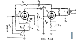
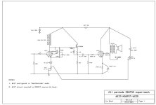
On the bench is a single-ended pentode (6CZ5). It’s configured with 36dB of negative feedback from the plate of the 6CZ6 to the cathode of the input valve. I dubbed this arrangement RDH733 after figure 7.33 in the Radiotron Designer’s Handbook. The RDH schematic shows negative feedback from plate to cathode in a two-stage amplifier. The input and output devices are both pentodes. The feedback loop does NOT include the output transformer.
RDH offers a mathematical analysis of the circuit to help estimate performance. The analysis is somewhat complicated by the feedback resistor Rk below the cathode resistor of the input pentode, which is not bypassed and provides additional negative feedback which reduces the input pentode’s gain. I used the RDH mathematics to put me in the ballpark and adopted a test circuit with potentiometers that allowed me to fine tune the feedback.
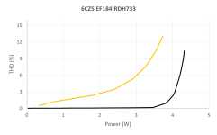
The chart shows total harmonic distortion on the vertical axis and output power on the horizontal axis for a 1kHz input signal. The orange line shows the result for a zero-feedback amp using the 6CZ5, the black curve with 36dB of negative feedback from plate to cathode. The negative feedback reduces distortion over a useful range of power.
I found I could get splendid test results (low distortion etc) that didn’t sound so good through my speakers. So I varied the overall feedback until I liked the sound, sometimes to the detriment of the measurements. As a rule of thumb, with my test speakers I achieved pleasing sound when I arranged THD to be 0.5% to 1.0% when the input signal was 1VRMS. The “sweet spot” will likely vary according to your speakers and your taste.
RDH offers a mathematical analysis of the circuit to help estimate performance. The analysis is somewhat complicated by the feedback resistor Rk below the cathode resistor of the input pentode, which is not bypassed and provides additional negative feedback which reduces the input pentode’s gain. I used the RDH mathematics to put me in the ballpark and adopted a test circuit with potentiometers that allowed me to fine tune the feedback.
The chart shows total harmonic distortion on the vertical axis and output power on the horizontal axis for a 1kHz input signal. The orange line shows the result for a zero-feedback amp using the 6CZ5, the black curve with 36dB of negative feedback from plate to cathode. The negative feedback reduces distortion over a useful range of power.
I found I could get splendid test results (low distortion etc) that didn’t sound so good through my speakers. So I varied the overall feedback until I liked the sound, sometimes to the detriment of the measurements. As a rule of thumb, with my test speakers I achieved pleasing sound when I arranged THD to be 0.5% to 1.0% when the input signal was 1VRMS. The “sweet spot” will likely vary according to your speakers and your taste.
Attachments
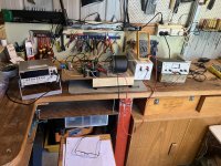
The schematic shows the arrangement on the bench, which has evolved as I have experimented. I used the 6CZ5 with the 6EJ7 in some tests, the 1L5G with the 6A4 in others. There are many potential combinations that might be interesting to experimenters.
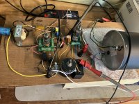
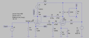
- The input valve is a 6EJ7 pentode (EF184 or 6F23) in this case configured as a screen cascode, a la Frank Blohbaum’s “Best Pentode”.
- The 6EJ7 is cathode biased with an infrared LED. This gave lower distortion than a capacitor-bypassed resistor.
- The anode of the 6EJ7 works into a choke, a 150H Hammond 156C. This gave significantly lower distortion that any resistor I used.
- I have interposed a MOSFET source-follower between the 6EJ7 and the 6CZ5. The 6EJ7 has a relatively high output impedance and was not able to drive the 6CZ5 much above 3W without significant distortion. The MOSFET driver provides low output impedance drive and adds another useful Watt to the output.
Attachments
Interesting!
What is the LF response of this amp? Or, what is the distortion at LF? At 20Hz, the choke offers only circa 19k load on the pentode.
Also, there is probably not a lot of voltage between drain and source of the IRF820. When the plate goes up, it will put the FET in the very capacitevely non-linear low VDS region - maybe a resistor in series with the choke to increase VDS over the fet?
I have been experimenting a lot lately with plate to cathode feedback and one can indeed get great measured results. As you, I do believe that lowest distortion may indeed not translate into "best sound", even though some orchestral work could probably benefit from less THD and IMD - but that is a whole other discussion.
Plate to cathode is voltage derived, voltage applied. However, the feedback is not applied to the same node as the input signal, which can cause unexpected effects not accounted for by simple feedback theory.Is plate to cathode feedback through capacitor the same as plate to plate feedback ? What are the differences?
Plate to plate is voltage derived, current applied. The driving tube has to drive the feedback resistor, which also looks smaller due to the bootstrapping effect. In other words the first tube has to drive a heavier load, making it's open-loop distortion worse. We might therefore expect plate-to-plate to deliver less distortion reduction and other benefits than plate to cathode, for the same amount of feedback applied.
In practice it can be difficult to make a fair comparison between the two approaches, because there is disagreement over what 'fair' would look like. Too many variables!
If you haven't already seen this thread, it has some schematics with plate to cathode feedback.
https://www.diyaudio.com/community/...ck-and-triode-connection.403110/#post-7450502
https://www.diyaudio.com/community/...ck-and-triode-connection.403110/#post-7450502
Interesting. What is best to avoid the non-linear influence of the cathode then? Ground it?I was told by someone knowledgeable that the cathode is a non-linear element. Which would make feedback there non-linear.
I mean, a lot of respected amplifiers seem to use the cathodes as part of feedback paths (Telefunken and the WEs shown in the previous posts, trifilar OPTs in McIntosh and I think a PP from Tim de Paravincini).
The driver tube input signal is the grid to cathode voltage. This feedback directly modulates the cathode voltage, driving current across a linear resistor, without altering the grid voltage from the preceding stage so the difference is not clear to me.the feedback is not applied to the same node as the input signal
I'm currently wiring up a similar circuit, minus follower, with a very significant difference in the sizes of cathode and feedback resistors and an active plate load. From memory about 17 dB of feedback. The 1 watt distortion is ~ 0.15% with only 2nd and 3rd above -90 dB. Plate-to-plate feedback didn't work nearly as well with a triode driver.
Attachments
You would have to use shunt feedback, applying feedback to the grid, like an inverting opamp configuration. It's not really an issue though, feedback to cathode still gives you most of the distortion reducing effect you would expect.Interesting. What is best to avoid the non-linear influence of the cathode then?
Interesting. What is best to avoid the non-linear influence of the cathode then?
I'm definitely no expert on the subject but this discussion rang a little bell. Please scroll down a bit to the schematic with the Fet below the cathode of the input tube, perhaps that is a solution? I'm quite sure the person behind this blog is a member here too: http://tubeswithatwist.blogspot.com/
The blocking capacitor (the 10uF "C block" in the schematic) strongly affects low frequency response and low frequency distortion. I experimented with lower values. They introduced an amplitude response that rose as frequency fell, a "hump" that looked attractive if I wanted a bass-boost, except that distortion also rose! The larger capacitor means that feedback stays effective with decreasing frequency.Interesting!
What is the LF response of this amp?
Thanks, Erik - I missed that thread. Neumann used a similar topology in the LV60 cutter-head amp, and the Telefunken amps I found include the V69, V73 and V81 - how did your V69 experiment go?If you haven't already seen this thread, it has some schematics with plate to cathode feedback.
https://www.diyaudio.com/community/...ck-and-triode-connection.403110/#post-7450502
In RDH, plate-to-cathode feedbak is described as "deservedly popular", though I didn't find that many single-ended applications. Interestingly, Bill Hewlett used it in the oscillator he described in his June 1939 thesis for his Stanford degree in electrical engineering - that design was the basis of his first commercial success.
Hi Fuling
Yep, I've seen that and it's a fine design.")
Stabilising the bias/gain of the input pentode is an issue, which I got around by using the "Best Pentode" topology which is quite docile.
I'm definitely no expert on the subject but this discussion rang a little bell. Please scroll down a bit to the schematic with the Fet below the cathode of the input tube, perhaps that is a solution?
Yep, I've seen that and it's a fine design.
Stabilising the bias/gain of the input pentode is an issue, which I got around by using the "Best Pentode" topology which is quite docile.
Miniwatt,
You said: "I was told by someone knowledgeable that the cathode is a non-linear element"
Take a look at a tube's family of curves:
The two axis of: Plate voltage and plate current; versus control grid voltage steps (each grid voltage step has a plate voltage/plate current curve).
Now, consider that you can either vary the grid voltage and hold the cathode voltage constant; or you can vary the cathode voltage and hold the grid voltage constant (with an increase in the plate voltage, so that the plate to cathode voltage is constant).
At the same cathode to plate voltage, and the same grid to cathode voltage, or the same cathode to grid voltage, the plate current will be the same.
All tubes are non-linear to some extent. True.
All tubes are linear to some extent. Also True.
How do you want to look at all of the above?
With blind faith?
With a grain of salt?
With understanding?
I was very interested in output tube plate to driver tubeplate Schade negative feedback.
I was also very interested in output tube plate to driver tube cathode negative feedback.
I tried both. They worked fairly well. With more adjustment they could have worked even better.
As a biased person, they were not really what topology that I want to use in my amplifier designs.
I no longer use either form of negative feedback.
For many others, it is one of their favored topology. Good.
Just my Opinions
Have fun with tube amplifiers!
Last edited:
Plate to Cathode NFB causes the output pentode to look like a triode.
That is OK but it always causes the output tube to be much more susceptible to power supply hum.
So the problem then simply moves to cleaning up the PS.
A simpler but far better solution is OPT secondary to previous tube cathode NFB.
That includes the OPT & helps to reduce non-linearity problems with the SE OPT.
Of the several of these type FB Pairs I've built using both triodes & pentodes I've always had good results.
Needs a bit of care selecting the interstage coupling cap, to large a cap might result in an LF hump response,
This is just NFB from primary , I don't see the purpose of some statements written here , as the principle is just the same as NFB from secondary to the cathode of the driver tube . The secondary is just the plate divided by the turn ratio . Hum is the same because now the feedback resistor has a much higher value
The advantage is that the transformer phase shift is not in the feedback loop
Usually there is no need for a series blocking capacitor as the feedback resistor has a significantly higher value for the same NFB in dB as from secondary , so the DC voltage from output stage plate is low . And you could change the the driver resistors values to take in account this DC voltage injected in the cathode .
Last edited:
Thanks Bondini,The blocking capacitor (the 10uF "C block" in the schematic) strongly affects low frequency response and low frequency distortion. I experimented with lower values. They introduced an amplitude response that rose as frequency fell, a "hump" that looked attractive if I wanted a bass-boost, except that distortion also rose! The larger capacitor means that feedback stays effective with decreasing frequency.
Have you also tested the frequency response of the amp without feedback? I am mostly curious how the pentode + choke load work, theoretically it shouldn't work (too low a load at LF), but the feedback can correct frequency response, at the expense of distortion?!
- Home
- Amplifiers
- Tubes / Valves
- Single ended pentode with plate-to-cathode feedback