@SpreadSpectrum talked about those topics on this forum.
Yes, I just couldn't remember his name when I posted. Looks like a very clever circuit to me, assuming the goal is a neutral sounding amp.
In Spice increasing the blocking cap from 0.33 uF to 330 uF makes almost no difference to the interstage or output response from 0.2 Hz to 20 Hz. The dominant RC constant appears to be between the feedback blocking capacitor and the feedback resistor, below 2 Hz in my example. While Spice uses an idealized OPT bench measurements didn't show any issues in the sub-sonics.Or use a capacitor in series with the feedback resistor (use a large capacitance....
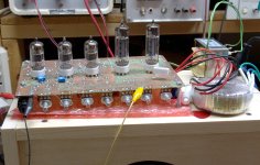
The build layout allows for easy conversion to secondary feedback if desired, plate-to-cathode was selected by ear and meter.
This might be of marginal interest, it is my now 13 year old take on a pentode SE amp with plate to cathode feedback. It's still in regular use. Thread is moderately long and long dead. Specific post showing the first successful implementation. Note this amp uses both plate to cathode feedback and global from the secondary of the output transformer.
https://www.diyaudio.com/community/threads/6v6-behavior-w-fixed-bias-se-amp.173454/#post-2302420
Cleaned up schematic: https://www.diyaudio.com/community/threads/6v6-behavior-w-fixed-bias-se-amp.173454/post-3707157
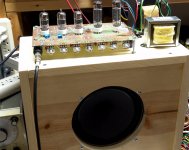
The amp was intended to a competitor in a local 5 tube SE stereo amp challenge, it was the only amp in the challenge that got built. It is also one of three tube amps still running here which maybe says something.
https://www.diyaudio.com/community/threads/6v6-behavior-w-fixed-bias-se-amp.173454/#post-2302420
Cleaned up schematic: https://www.diyaudio.com/community/threads/6v6-behavior-w-fixed-bias-se-amp.173454/post-3707157
The amp was intended to a competitor in a local 5 tube SE stereo amp challenge, it was the only amp in the challenge that got built. It is also one of three tube amps still running here which maybe says something.
Last edited:
Yep, the low frequency response goes WAY down with a big blocking cap (rumble filtering anyone?) plus LF distortion can be kept low. The blocking cap can be dispensed with (it works) but I restored it to make the set-up simpler when swapping different output valves for comparative testing. There is also the issue of managing the standing current in the OPT, so that dispensing with the blocking cap is less of an issue in the push-pull Telefunken designs referred to in earlier posts. As per usual, RDH733 is not a cure-all and involves trade-offs:Or use a capacitor in series with the feedback resistor (use a large capacitance, the gain goes up at the RC pole frequency, can either be a wanted bass lift, or undesired lift. Watch out for 3Hz record warp frequency, for example.
| Pro | Con |
| Simple to implement | The design maths are not so simple |
| Works best with high-gain devices | Most high gain devices are less linear to start with  |
| Lots of voltage gain allows lots of feedback | You’ll need all of it if you use cheap pentodes! |
| Easy to adjust feedback factor over wide range | That big blocking cap has gotta be audible! |
| OPT not in loop so doesn’t have to be “the best” | Can’t treat OPT distortion |
| Drives OPT from low impedance for less LF distortion | Duh - it's simpler to just use a triode |
| Very stable, even interposing a MOSFET/cathode follower | So what? So are other configurations |
My experiments are with cheap and cheerful output pentodes with high screen grid voltage ratings (I think I'll try UNSET when I come to play with big sweep tubes) and "not the best" OPTs. By way of interest, the EL84/6GK6 performs much like the 6CZ5 in my test rig ... perhaps I'll try a UL84 next ... or maybe some of my stash of 6V6 and 6L6 guitar amp "pulls".
For a power amp (the second-last device in the chain of music reproduction) I am comfortable trading away some of the low THD delivered by those 36dB of negative feedback if it means that the music sounds "right" to me through my speakers.
Last edited:
Sorry,
I guess I was not very clear about one of the negative feedback methods.
If you employ negative feedback by using a series RC from the output tube plate to the driver tube cathode self bias resistor (or the middle of a classical 2 resistor cathode series string traditionally used as the feedback node for cathode feedback), then . . .
There is no negative feedback at DC. It is open loop.
And the amount of negative feedback at high and mid frequencies is 3dB more than at the pole frequency of the series RC negative feedback network.
(The frequency where the capacitive reactance equals the series resistor).
This causes 'anything but' flat frequency response of the amplifier.
For the usual valves and (two stage single ended) gain structures that we're assuming, the resistor values don't really work out well for the dual requirements of DC bias for the first stage and for closed loop gain, when first stage grid is at 0VDC and no feedback DC blocking capacitor allowed. The solution in post #30 gives us some freedom of design, with the added benefit of a "super cathode bias" commonly specified for high performance wide-band amplifiers using valves of high transconductance (difficult to keep tolerances) but required to stabilize performance over the valve's life. The large cathode resistor gives a stable cathode current, approaching a CCS but slightly degraded by the feedback DC current, thus a fairly stable transconductance over life.
If DC elevating the first stage grid is not possible, and a feedback DC blocking cap must be used, then it needs to fit itself into the collection of other HP poles (and zeros - it's a zero in the loop). Ignoring power supply and cathode resistor bypass capacitor contributions (because they can and should be dealt with by brute force), the forward signal path has a pole at the first stage > second stage coupling cap with its associated resistances and a pole at the output valve "plate resistance" - OPT primary inductance junction, where we take our feedback. Without a feedback DC blocking cap, things are very straightforward - set a single dominant pole (the RC is by far the best choice) and done.
If the "reverse" (the feedback) path must have a pole (for DC blocking) it acts like a zero around the loop, so needs to be moved as far as possible from the dominant pole. Practically, its RC time constant needs to be a good order of magnitude greater than the dominant pole's (which, for other reasons, really should be the 1st > 2nd stage RC pole).
All good fortune,
Chris
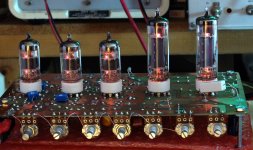
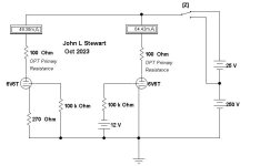
Another option could be to used fixed bias in the output stage as I did in the design below (details linked a couple of posts back). An A23 12V battery provides bias - one per channel.
Another option would be to include an input capacitor which would be outside of the feedback loop and would allow independent cathode bias in the input stage. The plate feedback resistor does make a significant contribution to the overall bias on the input stage.
Additional loop compensation was not required to my considerable surprise, normally I would have connected an empirically derived RC lag compensation network from the plate of the 6J7 to GND, but it was not required in this design. I initially had a lot of problems with this design, over the past decade or so and multiple tube changes I have not had to do anything. I change the batteries about every 5 years.
Looked at that but went with cathode bias because the 7591 permits use of a 1 meg grid resistor in that mode, double fixed bias. Full swing distortion of a CCS biased 6F5 stays nice and low, a fraction of 0.1% from memory.
Nice to see that circuit works well, the next project is a toss up between a Rowe amp rebuild or a 2-stage single ended pentode mode 828.
Nice to see that circuit works well, the next project is a toss up between a Rowe amp rebuild or a 2-stage single ended pentode mode 828.
That would be an interesting discussion!... Rowe amp rebuild ...
Aha! That was going to be the interesting part, using that centre tapped winding. When I proposed that idea here before, the people more experienced than me suggested it was a bit to much CFB for practical purposes, making it too hard to drive. I had been considering a tube with a low voltage screen requirement instead.convert the 70 volt winding to cathode feedback
Anyway, a discussion for another thread.
OldHector,
I am sure you are aware of the following (but just for Newbies that have now had their curiosity stimulated):
Very large voltage cathode negative feedback ideas are in multiple threads in Tubes/Valves.
McIntosh, and McIntosh ideas use Bootstrapped driver tubes that get their plate loads high voltage from the output tubes plates.
Positive feedback of bootstrapping is OK, when the rest of the circuits are linear, or when the total circuit is corrected, often by global negative feedback, or other methods.
The major difference between 70V cathode feedback versus is McIntosh, is the even larger voltage (unity coupled cathode & plate).
The above methods can not only be applied to push pull, with some circuit changes, they can also be applied to single ended.
Just remember that the UL84 is NOT a EL84/6BQ5 with a 45 volt 100 mA heater. It is a 45 volt 6CW5/EL86 which needs a much lower screen voltage to avoid becoming a flash - bang grenade.
My experiments are with cheap and cheerful output pentodes with high screen grid voltage ratings (I think I'll try UNSET when I come to play with big sweep tubes) and "not the best" OPTs. By way of interest, the EL84/6GK6 performs much like the 6CZ5 in my test rig ... perhaps I'll try a UL84 next ... or maybe some of my stash of 6V6 and 6L6 guitar amp "pulls".
This Marshall inspired guitar amp made over 20 watts with a pair of UL84's driven by some UCC85's. It used a 120V to 120V isolation transformer for power running all the heaters in series, a voltage doubler that made 335 volts for main B+ and a simple diode bridge to make 130 volts for the screen grids. An Antek toroidal power transformer is used for the OPT to meet the $100 parts cost in the Hundred Buck Amp Challenge that ran in the intruments and amps forum about 10 years ago. The amp made 25 watts with a 3300 ohm OPT designed for a guitar amp.
Attachments
convert the 70 volt winding to cathode feedback.
I don't have too much experience on my own on the subject but it has been mentioned several times on this forum that PP output stages with CFB can be prone to HF oscillations.
I have tested this that topology with two different pairs of toroid transformers that happened to have 2*115V primaries and multiple secondaries suitable for CFB and speaker and I've never noticed any ill behaviours, well aware that I don't have the measuring equipment to see what's going on at 10MHz or so.
Most of the commercially available PP OPTs with CFB windings seems to be toroids, probably due to tighter magnetic coupling and better symmetry or something.
Fuling,
Not to worry anybody, but . . .
Without proper design considerations, any form of negative feedback can be prone to HF oscillations.
Everybody's Mileage May Vary.
:^)
And, as long as output transformers are being discussed, for designers who use Ultra Linear circuits . . .
How many of them consider the leakage reactance from the UL tap to the Plate tap?
Phase shift of the UL tap to plate tap at high frequencies anybody?
Good transformers can be important for UL circuits (with, or without, global negative feedback); not just important for Pentode and Beam Power circuits that use global negative feedback.
Triode Wired pentodes or beam power tubes anybody?
Tradeoffs, tradeoffs, etc.
Last edited:
At this point not even sure if the quality of the 70 volt secondary is suitable for feedback. Does it tank at 8 kHz? Needs measuring. Fixed bias is preferable but if that doesn't work cathode biasing will provide a return resistor to load, pad and potentially shape the 70 volt winding signal. Still in shower thinking part of the process.it was a bit to much CFB
Just remember that the UL84 is NOT a EL84/6BQ5 with a 45 volt 100 mA heater. It is a 45 volt 6CW5/EL86 which needs a much lower screen voltage to avoid becoming a flash - bang grenade.
Yep, thanks Tubelab, on to that. And VERY interested in the UCC85/UL84 guitar amp - will PM you.
Fixed Bias is never a great idea for an SE stage running Class A.Another option could be to used fixed bias in the output stage
Both tube aging & power supply drift will create problems.
Here is a simple simulation of a 6V6 comparing fixed & cathode bias as the power supply changes. The 6V6 specs are taken from the RCA HB.
This could be internal to the amplifier or the power from the local utility.
Not to infer that anybodies primary PS is a problem, but in some jurisdictions it may be.
Especially if it is owned by a large group of stockholders whose primary interest is the system profits. And not its users.
The switch operated by the key 'Z' on the laptop changes the supply by 10%
The cathode biased 6V6 plate current changes by 11.9% while the fixed bias 6V6 plate current changes by 29%.
Something to think about.
I'll post something similar on tube aging later.
Attachments
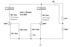
I got a request for the schematic of the amp, so it is included here. There are some caveats though. When I laid out this board, I used the "kitchen sink" approach. I put everything that I wanted to test out on the board except the kitchen sink.....that might put the project over budget.Yep, thanks Tubelab, on to that. And VERY interested in the UCC85/UL84 guitar amp - will PM you.
The mosfet and the two resistors connected to its gate that are in series with the cathode bypass caps on the UCC85 tubes were part of a variable gain experiment that did not work. Eliminate the mosfets, and gate resistors and put a resistor or jumper between the source and drain pins to connect the bypass cap.
There is far too much gain in the preamp. The Mu of the UCC85 tube is 46 or 50 depending on which data sheet you have. The typical 12AX7 has a Mu of 100, so I threw in an extra tube. Once I built and powered up the amp it was extremely microphonic and would distort at very low volume settings on the guitar leading to hum pickup. It was so sensitive that even moving the guitar cable made noise.
I removed the mosfet source follower buffer from all but the stage that drives the tone stack. It still had too much gain, so I simply bypassed one of the gain stages. That was about right.
If I ever went back to this design I would probably experiment with putting resistance in series with the cathode bypass caps (source to drain where the mosfets were).
The amp still sits on a shelf asking for attention, but has not been powered up in probably 10 years. It was a screamer when it worked, but was far too loud in my 100 square foot room when turned up high enough to get that Marshall sound. I det get an L pad attenuator to go between the amp and speaker but never got around to testing it much.
The power transformer was a simple 120 / 240 volt to 120 volt isolation transformer. The 50 VA Triad N68-X got far too hot so I had to use an 80 VA transformer. I don't remember its number.
Attachments
- Home
- Amplifiers
- Tubes / Valves
- Single ended pentode with plate-to-cathode feedback