Indeed, I think @SpreadSpectrum is the author. I had seen it, but forgotten, so many thanks for the reminder! I may indeed try it.I'm definitely no expert on the subject but this discussion rang a little bell. Please scroll down a bit to the schematic with the Fet below the cathode of the input tube, perhaps that is a solution? I'm quite sure the person behind this blog is a member here too: http://tubeswithatwist.blogspot.com/
For a lot of my experiments I use gyrator loads for either pentode or triode. Good load untHi Fuling
Yep, I've seen that and it's a fine design.
Stabilising the bias/gain of the input pentode is an issue, which I got around by using the "Best Pentode" topology which is quite docile.
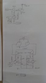
Well, I do a lot of experiments, and the V69 was mostly an inspiration. In some tests I used MOSFETs as gain stages instead of pentodes. What I use a lot are the gyrator loads, as these allow to keep the pentode's plate at a fixed voltage (contrary to CCS...), and to drive the output stage into A2. Attached you find the raw schematic of an 811 class A2 with EF184 gyrator loaded driver with plate to cathode feedback (on top). At the bottom gyrator loaded pentode's with feedback as originally presented by Schade. The resistors set roughly the gain, the mosfets drive the output triodes into class 2 (if desired). And variations on these themes.Thanks, Erik - I missed that thread. Neumann used a similar topology in the LV60 cutter-head amp, and the Telefunken amps I found include the V69, V73 and V81 - how did your V69 experiment go?
In RDH, plate-to-cathode feedbak is described as "deservedly popular", though I didn't find that many single-ended applications. Interestingly, Bill Hewlett used it in the oscillator he described in his June 1939 thesis for his Stanford degree in electrical engineering - that design was the basis of his first commercial success.
Attachments
Triode wiring a pentode is also a form of feedback, which I sometimes use as well. WRT of the increased noise, nowadays filtering the B+ is easy (I like source follower capacitance multiplier with a raw current limiter: clean DC, slow startup, current limiting), big caps are also available.
Yes, the blog belongs to member SpreadSpectrumI'm definitely no expert on the subject but this discussion rang a little bell. Please scroll down a bit to the schematic with the Fet below the cathode of the input tube, perhaps that is a solution? I'm quite sure the person behind this blog is a member here too: http://tubeswithatwist.blogspot.com/
https://www.diyaudio.com/community/threads/shunt-feedback-6384-se-amp.354046/
The SSE amp that I came up with almost 20 years ago has the ability (via jumper selection) to connect the output tube's cathode bypass cap to the top of the secondary of the OPT with the bottom of the secondary grounded. This works wonders on some budget OPT's and lowers the DF of the amp.Plate to Cathode NFB causes the output pentode to look like a triode.
That is OK but it always causes the output tube to be much more susceptible to power supply hum.
So the problem then simply moves to cleaning up the PS.
A simpler but far better solution is OPT secondary to previous tube cathode NFB.
That includes the OPT & helps to reduce non-linearity problems with the SE OPT.
Of the several of these type FB Pairs I've built using both triodes & pentodes I've always had good results.
Needs a bit of care selecting the interstage coupling cap, to large a cap might result in an LF hump response,")
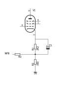
As mentioned in the blog, my UNSET design uses a resistive divider from the tube's plate directly to G1 with a resistor from G1 to ground. I find that a resistor ratio of about 10 to 1 provided enough feedback to get nice triode curves from a TV sweep tube. The drive and bias voltage is applied to the cathode via a P channel mosfet follower. This keeps the drive and feedback paths separate which avoids the input impedance fluctuations that occur when both paths meet.
See the simplified schematic in post #1 here for a full amplifier using this technology:
https://www.diyaudio.com/community/threads/unset-beta-board-build.376124/
The current from the feedback resistor injected into the driver cathode load alters the driver's bias voltage. It adds a significant constraint balancing driver operating point against total available feedback. I benched it quite a bit guided by a spreadsheet covering the full range of operating possibilities before DC blocking. Maybe the highest gain drivers can get away with it but the 6F5 isn't exactly low on the scale. Maybe a pentode mode driver?Usually there is no need for a series blocking capacitor as the feedback resistor has a significantly higher value for the same NFB in dB as from secondary , so the DC voltage from output stage plate is low .
6A3sUMMER, you didn't like this kind of local feedback for a specific reason?As a biased person, they were not really what topology that I want to use in my amplifier designs.
I no longer use either form of negative feedback.
For many others, it is one of their favored topology. Good.
You can tweak the plate/cathode resistor for optimal bias again , after all nobody said that this a magical simple solution to modify in any existing amplifierThe current from the feedback resistor injected into the driver cathode load alters the driver's bias voltage. It adds a significant constraint balancing driver operating point against total available feedback. I benched it quite a bit guided by a spreadsheet covering the full range of operating possibilities before DC blocking. Maybe the highest gain drivers can get away with it but the 6F5 isn't exactly low on the scale. Maybe a pentode mode driver?
And probably you wouldn't want another capacitor ( phase shift ) after you removed the output transformer from feedback loop
That is why I bias the pentode's grid at circa 6V, so there is enough voltage from cathode to ground to accomodate the extra current coming from the feedback resistor - but I am not that picky about the actual current through the driver tube, +-2mA from the expected value is good enough
Attachments

If the design isn't compromised by the revised plate load. In the example above it's a CCS so sure, altering driver current and plate load away from values already presumably optimized to add this form of feedback is an option to avoid a small film cap. As already noted the entire feasible range of cathode R and feedback R were investigated. Simple circuit constraints limited the available feedback degeneration available with a realizable DC topology.You can tweak the plate/cathode resistor for optimal bias again
LTSpice just happens to open to this circuit. Driver Ip is obviously constant due to the CCS. DC values:
AC coupled FB: 6F5 plate - 195 V, 6F5 cathode - 1.95 V , Rfb current - 0 ma
DC coupled FB: 6F5 plate - 365 V, 6F5 cathode - 2.9 V , Rfb current - 1.36 ma
The very large plate feedback resistor relative to the cathode resistor means the current injected from plate to cathode resistor is essentially constant across any realizable values of the latter. The only way to bring the driver back to the desired operating point is by limiting applied feedback. It's an engineering trade off.
The relevance to magic and existing amps, don't know.
If you don't want to change nothing more than 1 feedback resistor , than maybe you should buy an already modified amplifier ...
The cathode resistor should be split like it is in many designs using a bypass capacitor , if the part that is in NFB loop is small in value , than the DC has very little effect and you don't need to rebias the driver
The cathode resistor should be split like it is in many designs using a bypass capacitor , if the part that is in NFB loop is small in value , than the DC has very little effect and you don't need to rebias the driver
Last edited:
I have never been a fan of large amounts of GNFB in any amplifier. I strive to make a good sounding amp without feedback and then apply as little feedback as needed via the shortest possible path to clean it up. The usual worst offenders in the "needs help" department are the output devices and the OPT. I have used feedback from the secondary of the OPT to the output tube cathode to make a $30 OPT sound "better than it cost" in the SSE and other amps. If the OPT has multiple impedance taps on the secondary you can try them all to hear the effect. This type of feedback works to make cheap transformers sound good but does little on a good OPT that is fed by a decent low impedance output tube. The 300B has a low plate resistance and a wide "sweet spot" which is why there are so many 300B amps. You really have to try to make a bad sounding 300B amp!Thank you for your replies and links.
I wonder if for a simple 2 stages amplifier and IF the driver is linear and with sufficient gain, the better NFB is the shorter? ie: plate to grid of output tube only.
I had been tinkering with various non standard feedback paths off and on foe several years. I made a few test boards with a P / N channel mosfet pair on every element of a pentode except for the plate and heater. This could be used for applying DC voltage with a superimposed AC drive, feedback or both signal present. I built a board with a 12 pin compactron socket for playing with big sweep tubes, and a smaller perf board with a 7 pin and 9 pin miniature socket for the small stuff.
I screwed up and put the tube socket on the wrong side, so I simply added a second tube on the other side.
I often just tried random stupid ideas to see what would happen or played with a circuit in LT Spice before breadboarding it up. I tried two stage amps with several different feedback paths, or more than one path at the same time to see what they did. Two that have not been mentioned here yet are a resistor from output tube plate to the driver tube plate, or a resistor from the output tube plate to the driver tube screen grid.
It has been said that plate to plate feedback doesn't work with a triode driver, but my little SPUD board worked quite well with this kind of feedback.
There was a discussion about reducing the cost of a typical guitar amp that was scattered across several threads in the instruments and amps forum that set me on a course that led to the development of the UNSET design. The original reason for the research was to eliminate the negative voltage bias supply in fixed bias amps. The first "success" was this little guitar amp breadboard that extracted 20 watts from a pair of tiny 50C5 radio tubes in push pull from a single rail power supply of 330 volts derived from a voltage doubler on the output of a Triad N-68X isolation transformer.
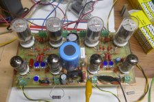
That led to a little stereo amp that squeezed 80 WPC at 3% THD from two pair of $1 tubes (6GF5) being driven by another pair of $1 tubes (6KT6) on a 500 volt regulated bench supply. The same board made 60 WPC when powered by an Antek toroidal power transformer. The performance and sound quality was excellent, so UNSET was born.
The last picture shows the collection of boards and experiments that got to this point.
Attachments
-
 P1850356.JPG278.2 KB · Views: 40
 -
 P1850355.JPG247.8 KB · Views: 33
 -
 P1850371.JPG324.9 KB · Views: 29
 -
 P1850357.JPG415 KB · Views: 36
 -
 P3730055.JPG577 KB · Views: 34
 -
 Spud_Amp_1.jpg101.4 KB · Views: 35
 -
 PCboard.jpg126.3 KB · Views: 40
 -
 P4010496.JPG179.6 KB · Views: 40
 -
 P1850392.JPG496.5 KB · Views: 46
I believe that output-tube plate to driver-tube plate Schade negative feedback also causes pentode tubes and beam power tubes to look more like a triode, it reduces the output tube plate impedance, rp.
More susceptible to B+ ripple?
Always start with a good B+ supply.
Change one thing, and get 2 more changes along with it.
1 step forward, and 2 steps backward.
One time, as usual, I started with a low ripple B+.
Then I used a choke as the CCS of an "LTP" phase splitter, to drive the push pull output tubes.
Unfortunately, there was lots of magnetic coupling from the B+ choke to the "CCS LTP" choke.
It caused common mode hum, so you did not hear it.
But the '"silent" common mode hum robbed a significant amount of power from the output stage, with the push and pull tubes currents increasing and decreasing in-phase, at the rate of the magnetic signal of the B+ filter choke.
The two chokes had to be separated, and rotated for the correct angle to get rid of the magnetic coupling.
Live and Learn
Thanks. While that works it replaces, in my example, a 0.33 uF polypropylene in the signal path with a large electrolytic. Boils down to personal choice but not my preference. Still not seeing how your second suggestion would work.This are typical values
emk2,
I was not a fan of Schade negative feedback, because it puts a low impedance load on the driver tube.
You can use a pentode driver, which is usually the best tube for Schade circuits. I generally only use triode driver tubes.
If you use a triode as the driver, you can use an un-bypassed self bias resistor to raise the triode's rp, but that reduces the gain.
There is an excellent example using a 12AT7, parallel 807s, and Monolith Magnetics output transformers. I can not remember the name of the site, or the name of the builder (Saras?).
If you use output tube plate to driver cathode negative feedback, you have 2 options:
Either a very intelligently designed multi resistor DC coupled negative feedback circuit,
Or use a capacitor in series with the feedback resistor (use a large capacitance, the gain goes up at the RC pole frequency, can either be a wanted bass lift, or undesired lift. Watch out for 3Hz record warp frequency, for example.
I prefer more straight signal paths, and more local negative feedback, such as triode wiring the beam power or pentode output tubes.
I have also used and enjoyed Ultra Linear opertation of the beam power and pentode output tubes.
Personal preferences.
To cast my preferences in concrete and forbid others to use other topologies and methods is not my desire:
"For any engineering problem there are 100 solutions, of which at least 3 will work . . . but only if they are implemented properly"
@SpreadSpectrum talked about those topics on this forum.I'm quite sure the person behind this blog is a member here too: http://tubeswithatwist.blogspot.com/
- Home
- Amplifiers
- Tubes / Valves
- Single ended pentode with plate-to-cathode feedback