Hi to all;
I'm student from the Philippines, I'm taking up two courses BSCS(Bachelor of science in computer science 3rd yr.) and ECE 2yr student,as of now I just experienced how to make a project using microcontroller, creating firmware and ide software, interfacing nokiaLCD and others,
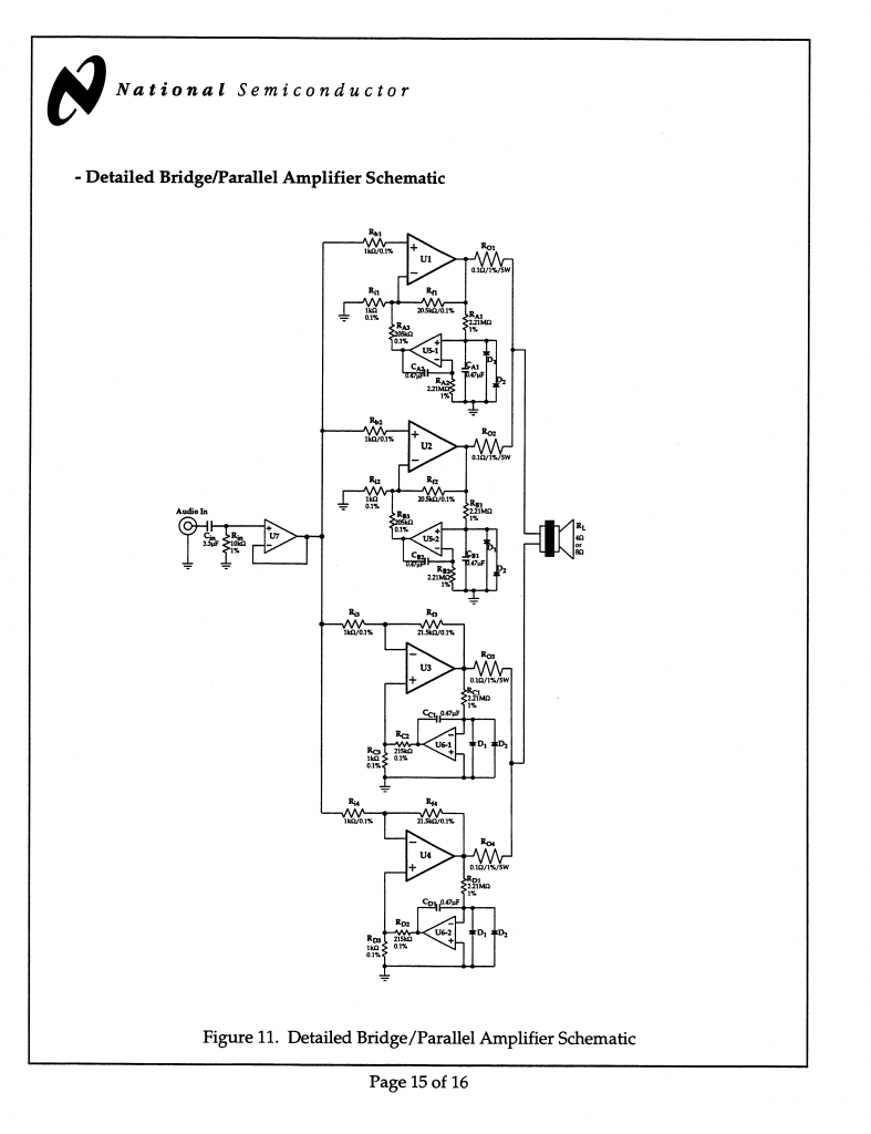
I want to exercise my knowledge to the next level, since we're on simbreak, I want to Build DIY amplifier, I have alot of reading about BPA200 using LM3886, but I have no luck in searching the complete detailed Diagram.
can anybody here give/send to me the copy of complete schematic of bpa200 using lm3886. thanks
any comment(s) is really appreciated
here my email: cresswood2@gmail.com
I'm student from the Philippines, I'm taking up two courses BSCS(Bachelor of science in computer science 3rd yr.) and ECE 2yr student,as of now I just experienced how to make a project using microcontroller, creating firmware and ide software, interfacing nokiaLCD and others,
I want to exercise my knowledge to the next level, since we're on simbreak, I want to Build DIY amplifier, I have alot of reading about BPA200 using LM3886, but I have no luck in searching the complete detailed Diagram.
can anybody here give/send to me the copy of complete schematic of bpa200 using lm3886. thanks
any comment(s) is really appreciated
here my email: cresswood2@gmail.com
Last edited:
I suppose this might be something like what you're looking for.
http://www.ti.com/litv/pdf/snaa021b
All I did was Google bpa400
http://www.ti.com/litv/pdf/snaa021b
All I did was Google bpa400
I suppose this might be something like what you're looking for.
http://www.ti.com/litv/pdf/snaa021b
All I did was Google bpa400
thanks for response;
I'd already read that documentation, and also I found this diagram that more detailed,
bcoz I'm newbie,I think I need more detailed,.
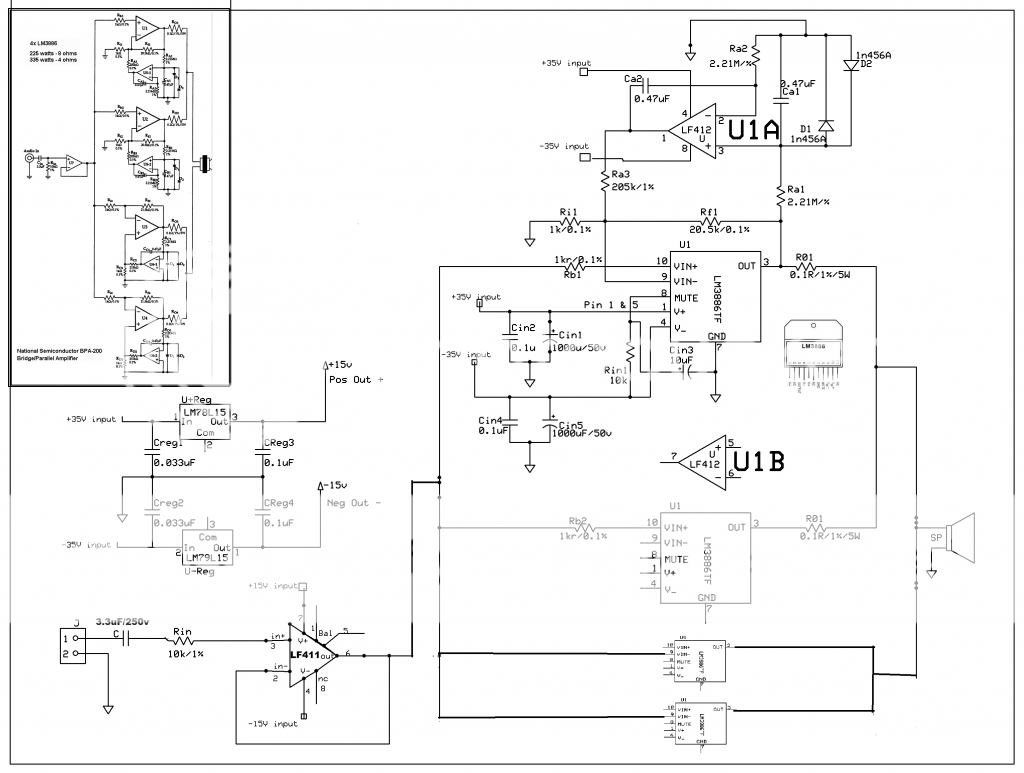
In the Diagram that I posted, I can't see the tie-up connection between the Capacitors,78L15 positive regulator, 79L15 negative regulator. and so on.
Last edited:
I really think that you should read up on basic electronics before attempting to build something like this. Because if you don't know how to wire up a basic OP-amp then building a BPA200 amp that works might be a bit to much.
But I shall not rain on your parade")
I attached a PDF-file of a schematic that I have made. Now, there is some notes you must now. I have not tested it nor built this specific version. I have double-checked it but there might still be some errors. Grounds are not separated and it uses a groundplane. This is not liked by many members on this forum, it have worked well for me in other designs but it might not work for you if you build it. To be honest its impossible to use a star-ground on a two layer design of this size. Also, component values might have to be changed. I will not explain that further, all information about why and how is available in the PDF previously linked and in basic audio design around the web.
EDIT: Ground are in fact somewhat separated.
But I shall not rain on your parade
I attached a PDF-file of a schematic that I have made. Now, there is some notes you must now. I have not tested it nor built this specific version. I have double-checked it but there might still be some errors. Grounds are not separated and it uses a groundplane. This is not liked by many members on this forum, it have worked well for me in other designs but it might not work for you if you build it. To be honest its impossible to use a star-ground on a two layer design of this size. Also, component values might have to be changed. I will not explain that further, all information about why and how is available in the PDF previously linked and in basic audio design around the web.
EDIT: Ground are in fact somewhat separated.
Attachments

Last edited:
I agree with CJ.
Build a single chip version of a chipamp first.
Get it working, then get it working properly, so that there is no measured hum, no buzz, no interference from your WiFi and mobile phone, no measured instability when a range of small capacitances are added to the 8r0 dummy load.
Build a copy of the final well behaved version.
Join them together to create a stereo amplifier and find all the problems that 2channel brings to the assembly.
When you have learned to sort all that out, you might be ready to look at some or one of National's multi-chip amplifiers.
BA100, PA100 and BPA200 are complex assemblies that result in many failed amplifiers and in very many requests for help on this Forum.
BTW, getting the simple dual polarity PSU right is probably the biggest problem you will have. It is certainly the BIGGEST problem on this Forum !!!
In the Diagram that I posted, I can't see the tie-up connection between the Capacitors,78L15 positive regulator, 79L15 negative regulator. and so on.
If you're an engineering student, you better get used to looking up the data sheets for the various components. Look up those for the LM78L15 and LM79L15. Read them. Figure out which components you need to put around them to make them work. I've linked to the product page for the LM78L15. I'm sure you can find the one for the LM79L15...
I really think that you should read up on basic electronics before attempting to build something like this. Because if you don't know how to wire up a basic OP-amp then building a BPA200 amp that works might be a bit to much.
I agree.
Grounds are not separated and it uses a groundplane. This is not liked by many members on this forum
You get the best performance by using a ground plane. If you want to get fancy, you connect the feedback ground and input ground to the output ground by a separate plane. The reason ground planes work is that they minimize the inductance, hence, the impedance of the ground connections. This is the only way to ensure that you get the published performance of the LM3886. Anything else will cause a rise in THD at higher frequencies (sometimes starting as low as 1-2 kHz). I have a stack of measurements to back this up...
~Tom
^ thanks for your comment sir but I still I can't figure out what is the causes why it blows-up. your comment is like a puzzle to me
"blows-up"
-It because I used +-35v to lf412 opamp?
-or I better change to +-15v the input voltage of LF412?
- or(and) I need another 2 IC +-15v regulator for more amperes?
"blows-up"
-It because I used +-35v to lf412 opamp?
-or I better change to +-15v the input voltage of LF412?
- or(and) I need another 2 IC +-15v regulator for more amperes?
First, have you not read the data sheet for the LF412? Supply voltage is no more than +/- 22V. Connecting it to 35V will fry the LF412 and a result of that is that it will fry the rest of your amp.
Also, your schematic does not show a bridged/parallel amp. It shows an (unfinished) paralleled amp. What is it that you want to build?
Dont be afraid to build stuff. We all learn from our mistakes but please, listen to our advices. It will save you time, money and frustration. Me, Andrew and Tom has all advised you to read up, and clearly that is something you haven't done.
Everything you need to know about how to build the amp is in the document from TI/National. But if you don't understand it, which you obviously don't to, then try to learn.
^CJ900RR
I just showing the part of full schematic, if the circuit of 1 IC(lm3886) is correct, it was easy for me to build the whole diagram. thanks for advice.
Also, your schematic does not show a bridged/parallel amp. It shows an (unfinished) paralleled amp. What is it that you want to build?
I just showing the part of full schematic, if the circuit of 1 IC(lm3886) is correct, it was easy for me to build the whole diagram. thanks for advice.
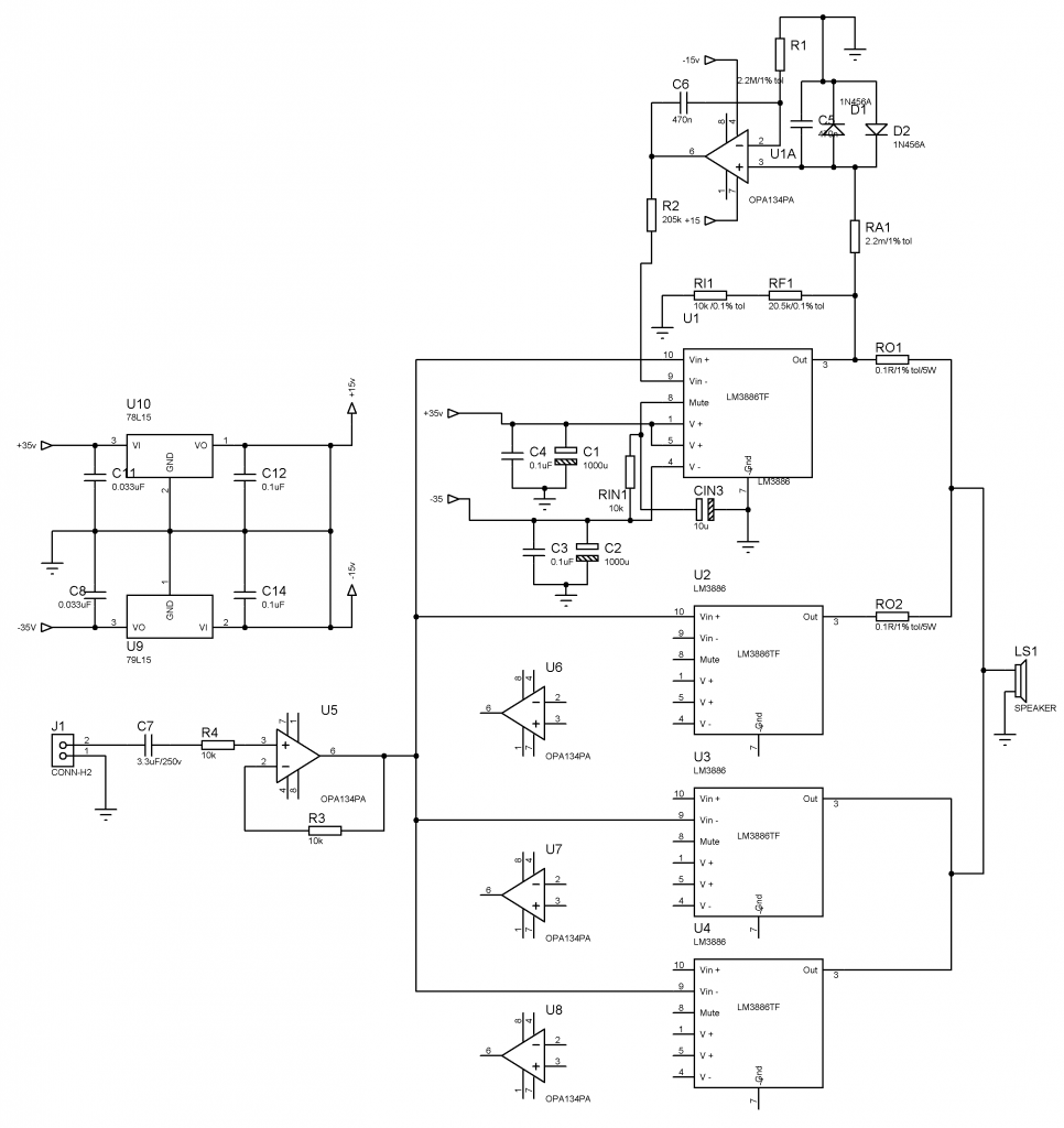
That schematic will not work. Do your homework. And it's still a paralleled amp only, not a bridged/parallel.
Honestly? Did you not read the data sheets for the voltage regulators? How much mAh can the 78 and 79 L provide? How much does every OP draw in worst case scenario? How much mAh does 4 of that add up to? Come on, your not even trying.
Honestly? Did you not read the data sheets for the voltage regulators? How much mAh can the 78 and 79 L provide? How much does every OP draw in worst case scenario? How much mAh does 4 of that add up to? Come on, your not even trying.
- Home
- Amplifiers
- Chip Amps
- BPA200 (LM3886TF) Detailed Diagram